COPY No. |
|||
|
|||
C.B. 04051 (103) |
|||
Interrogation of U-Boat Survivors |
|||
Cumulative Edition |
|||
June, 1944 |
|||
|
|||
C.B. 04051 (103) |
|||
Interrogation of U-Boat Survivors |
|||
Cumulative Edition |
|||
June, 1944 |
|||
|
|||
| INTELLIGENCE DIVISION | |||
ADMIRALTY, S.W.I. |
|||
| N.I.D. 04045/44. | |||
3 |
|||||||||||||||||||||||||||||||||||||||||||||||||||||||||||||||||||||||||||||||||||||||||||||||||||||||||||||||||||||||||||||||||||||||||||||||||||||||||||||||||||||||||||||||||||||||||||||||||||||||||||||||||||||||||||||||||||||||||||||||||||||||||||||||||||||||||||||||||||||||||||||||||||||||||||||||||||||||||||||||||||||||||||||||||||||||||||||||||||||||||||||||||||||||||||||||||||||||||||||||||||||||||||||||||||||||||||||||||||||||||||||||||||||||||||||||||||||||||||||||||||||||||||||||||||||||||||||||||||||||||||||||||||||||||||||||||||||||||||||||||||||||||||||||||||||||||||||||||||||||||||||||||||||||||||||||||||||||||||||||||||||||||||
CONTENTS |
|||||||||||||||||||||||||||||||||||||||||||||||||||||||||||||||||||||||||||||||||||||||||||||||||||||||||||||||||||||||||||||||||||||||||||||||||||||||||||||||||||||||||||||||||||||||||||||||||||||||||||||||||||||||||||||||||||||||||||||||||||||||||||||||||||||||||||||||||||||||||||||||||||||||||||||||||||||||||||||||||||||||||||||||||||||||||||||||||||||||||||||||||||||||||||||||||||||||||||||||||||||||||||||||||||||||||||||||||||||||||||||||||||||||||||||||||||||||||||||||||||||||||||||||||||||||||||||||||||||||||||||||||||||||||||||||||||||||||||||||||||||||||||||||||||||||||||||||||||||||||||||||||||||||||||||||||||||||||||||||||||||||||||
|
|||||||||||||||||||||||||||||||||||||||||||||||||||||||||||||||||||||||||||||||||||||||||||||||||||||||||||||||||||||||||||||||||||||||||||||||||||||||||||||||||||||||||||||||||||||||||||||||||||||||||||||||||||||||||||||||||||||||||||||||||||||||||||||||||||||||||||||||||||||||||||||||||||||||||||||||||||||||||||||||||||||||||||||||||||||||||||||||||||||||||||||||||||||||||||||||||||||||||||||||||||||||||||||||||||||||||||||||||||||||||||||||||||||||||||||||||||||||||||||||||||||||||||||||||||||||||||||||||||||||||||||||||||||||||||||||||||||||||||||||||||||||||||||||||||||||||||||||||||||||||||||||||||||||||||||||||||||||||||||||||||||||||||
35787 A 2
|
|||||||||||||||||||||||||||||||||||||||||||||||||||||||||||||||||||||||||||||||||||||||||||||||||||||||||||||||||||||||||||||||||||||||||||||||||||||||||||||||||||||||||||||||||||||||||||||||||||||||||||||||||||||||||||||||||||||||||||||||||||||||||||||||||||||||||||||||||||||||||||||||||||||||||||||||||||||||||||||||||||||||||||||||||||||||||||||||||||||||||||||||||||||||||||||||||||||||||||||||||||||||||||||||||||||||||||||||||||||||||||||||||||||||||||||||||||||||||||||||||||||||||||||||||||||||||||||||||||||||||||||||||||||||||||||||||||||||||||||||||||||||||||||||||||||||||||||||||||||||||||||||||||||||||||||||||||||||||||||||||||||||||||
4 |
|||||||||||||||||||||||||||||||||||||||||||||||||||||||||||||||||||||||||||||||||||||||||||||||||||||||||||||||||||||||||||||||||||||||||||||||||||||||||||||||||||||||||||||||||||||||||||||||||||||||||||||||||||||||||||||||||||||||||||||||||||||||||||||||||||||||||||||||||||||||||||||||||||||||||||||||||||||||||||||||||||||||||||||||||||||||||||||||||||||||||||||||||||||||||||||||||||||||||||||||||||||||||||||||||||||||||||||||||||||||||||||||||||||||||||||||||||||||||||||||||||||||||||||||||||||||||||||||||||||||||||||||||||||||||||||||||||||||||||||||||||||||||||||||||||||||||||||||||||||||||||||||||||||||||||||||||||||||||||||||||||||||||||||||||||||||||||||||||||||||||||||||||||||||||||||||||||||||||||||||||||||||||||||||||||||||||||||||||||||||||||||||||||||||||||||||||||||||||||||||||||||||||||||||||||||||||||||||||||||||||||||||||||||||||||||||||||||||||||||||||||||||||||||||||||||||||||||||||||
|
|||||||||||||||||||||||||||||||||||||||||||||||||||||||||||||||||||||||||||||||||||||||||||||||||||||||||||||||||||||||||||||||||||||||||||||||||||||||||||||||||||||||||||||||||||||||||||||||||||||||||||||||||||||||||||||||||||||||||||||||||||||||||||||||||||||||||||||||||||||||||||||||||||||||||||||||||||||||||||||||||||||||||||||||||||||||||||||||||||||||||||||||||||||||||||||||||||||||||||||||||||||||||||||||||||||||||||||||||||||||||||||||||||||||||||||||||||||||||||||||||||||||||||||||||||||||||||||||||||||||||||||||||||||||||||||||||||||||||||||||||||||||||||||||||||||||||||||||||||||||||||||||||||||||||||||||||||||||||||||||||||||||||||||||||||||||||||||||||||||||||||||||||||||||||||||||||||||||||||||||||||||||||||||||||||||||||||||||||||||||||||||||||||||||||||||||||||||||||||||||||||||||||||||||||||||||||||||||||||||||||||||||||||||||||||||||||||||||||||||||||||||||||||||||||||||||||||||||||||
5 |
|||||||||||||||||||||||||||||||||||||||||||||||||||||||||||||||||||||||||||||||||||||||||||||||||||||||||||||||||||||||||||||||||||||||||||||||||||||||||||||||||||||||||||||||||||||||||||||||||||||||||||||||||||||||||||||||||||||||||||||||||||||||||||||||||||||||||||||||||||||||||||||||||||||||||||||||||||||||||||||||||||||||||||||||||||||||||||||||||||||||||||||||||||||||||||||||||||||||||||||||||||||||||||||||||||||||||||||||||||||||||||||||||||||||||||||||||||||||||||||||||||||||||||||||||||||||||||||||||||||||||||||||||||||||||||||
|
|||||||||||||||||||||||||||||||||||||||||||||||||||||||||||||||||||||||||||||||||||||||||||||||||||||||||||||||||||||||||||||||||||||||||||||||||||||||||||||||||||||||||||||||||||||||||||||||||||||||||||||||||||||||||||||||||||||||||||||||||||||||||||||||||||||||||||||||||||||||||||||||||||||||||||||||||||||||||||||||||||||||||||||||||||||||||||||||||||||||||||||||||||||||||||||||||||||||||||||||||||||||||||||||||||||||||||||||||||||||||||||||||||||||||||||||||||||||||||||||||||||||||||||||||||||||||||||||||||||||||||||||||||||||||||||
6 |
||||||||||||||||||||||||||||||||||||||||||||||||||||||||||||||||||||||||||||||||||||||||||||||||||||||||||||||||||||||||||||||||||||||||||||||||||||||||||||||||||||||||||||||||||||||||||||||||||||||||||||||||||||||||||||||||||||||||||||||||
CHAPTER I |
||||||||||||||||||||||||||||||||||||||||||||||||||||||||||||||||||||||||||||||||||||||||||||||||||||||||||||||||||||||||||||||||||||||||||||||||||||||||||||||||||||||||||||||||||||||||||||||||||||||||||||||||||||||||||||||||||||||||||||||||
U-BOAT TYPES AND SPECIFICATIONS |
||||||||||||||||||||||||||||||||||||||||||||||||||||||||||||||||||||||||||||||||||||||||||||||||||||||||||||||||||||||||||||||||||||||||||||||||||||||||||||||||||||||||||||||||||||||||||||||||||||||||||||||||||||||||||||||||||||||||||||||||
| (i) (a) Summary of Standard U-boat types and Foreign Submarines in German Service. | ||||||||||||||||||||||||||||||||||||||||||||||||||||||||||||||||||||||||||||||||||||||||||||||||||||||||||||||||||||||||||||||||||||||||||||||||||||||||||||||||||||||||||||||||||||||||||||||||||||||||||||||||||||||||||||||||||||||||||||||||
|
||||||||||||||||||||||||||||||||||||||||||||||||||||||||||||||||||||||||||||||||||||||||||||||||||||||||||||||||||||||||||||||||||||||||||||||||||||||||||||||||||||||||||||||||||||||||||||||||||||||||||||||||||||||||||||||||||||||||||||||||
| (i) (b) Foreign Submarines in German Service. | ||||||||||||||||||||||||||||||||||||||||||||||||||||||||||||||||||||||||||||||||||||||||||||||||||||||||||||||||||||||||||||||||||||||||||||||||||||||||||||||||||||||||||||||||||||||||||||||||||||||||||||||||||||||||||||||||||||||||||||||||
| (a) U.A. ex Turkish "BATIRAY" | ||||||||||||||||||||||||||||||||||||||||||||||||||||||||||||||||||||||||||||||||||||||||||||||||||||||||||||||||||||||||||||||||||||||||||||||||||||||||||||||||||||||||||||||||||||||||||||||||||||||||||||||||||||||||||||||||||||||||||||||||
| (b) U.B. Series ex Norwegian Submarines. | ||||||||||||||||||||||||||||||||||||||||||||||||||||||||||||||||||||||||||||||||||||||||||||||||||||||||||||||||||||||||||||||||||||||||||||||||||||||||||||||||||||||||||||||||||||||||||||||||||||||||||||||||||||||||||||||||||||||||||||||||
| (c) U.D. " ex Netherlands Submarines. | ||||||||||||||||||||||||||||||||||||||||||||||||||||||||||||||||||||||||||||||||||||||||||||||||||||||||||||||||||||||||||||||||||||||||||||||||||||||||||||||||||||||||||||||||||||||||||||||||||||||||||||||||||||||||||||||||||||||||||||||||
| (d) U.E. " ex British Submarines. | ||||||||||||||||||||||||||||||||||||||||||||||||||||||||||||||||||||||||||||||||||||||||||||||||||||||||||||||||||||||||||||||||||||||||||||||||||||||||||||||||||||||||||||||||||||||||||||||||||||||||||||||||||||||||||||||||||||||||||||||||
| (e) U.F. " ex French Submarines. | ||||||||||||||||||||||||||||||||||||||||||||||||||||||||||||||||||||||||||||||||||||||||||||||||||||||||||||||||||||||||||||||||||||||||||||||||||||||||||||||||||||||||||||||||||||||||||||||||||||||||||||||||||||||||||||||||||||||||||||||||
| (f) U.T. " ex French Submarines. | ||||||||||||||||||||||||||||||||||||||||||||||||||||||||||||||||||||||||||||||||||||||||||||||||||||||||||||||||||||||||||||||||||||||||||||||||||||||||||||||||||||||||||||||||||||||||||||||||||||||||||||||||||||||||||||||||||||||||||||||||
| (g) U.I. " ex Italian Submarines. | ||||||||||||||||||||||||||||||||||||||||||||||||||||||||||||||||||||||||||||||||||||||||||||||||||||||||||||||||||||||||||||||||||||||||||||||||||||||||||||||||||||||||||||||||||||||||||||||||||||||||||||||||||||||||||||||||||||||||||||||||
| For full details of above see C.B. 1815. | ||||||||||||||||||||||||||||||||||||||||||||||||||||||||||||||||||||||||||||||||||||||||||||||||||||||||||||||||||||||||||||||||||||||||||||||||||||||||||||||||||||||||||||||||||||||||||||||||||||||||||||||||||||||||||||||||||||||||||||||||
| (ii) General | ||||||||||||||||||||||||||||||||||||||||||||||||||||||||||||||||||||||||||||||||||||||||||||||||||||||||||||||||||||||||||||||||||||||||||||||||||||||||||||||||||||||||||||||||||||||||||||||||||||||||||||||||||||||||||||||||||||||||||||||||
| (a) Armament of U-Boats and conning tower layouts are described in Chapter II. | ||||||||||||||||||||||||||||||||||||||||||||||||||||||||||||||||||||||||||||||||||||||||||||||||||||||||||||||||||||||||||||||||||||||||||||||||||||||||||||||||||||||||||||||||||||||||||||||||||||||||||||||||||||||||||||||||||||||||||||||||
| (b) The actual displacement of every type exceed the standard displacement, e.g. that of Standard 500 Type VII C is 784 tons surfaced and 883 submerged. | ||||||||||||||||||||||||||||||||||||||||||||||||||||||||||||||||||||||||||||||||||||||||||||||||||||||||||||||||||||||||||||||||||||||||||||||||||||||||||||||||||||||||||||||||||||||||||||||||||||||||||||||||||||||||||||||||||||||||||||||||
| (c) The normal thickness of pressure hulls of 7/8 ins. tapering to 11/16 towards the bow and stern. | ||||||||||||||||||||||||||||||||||||||||||||||||||||||||||||||||||||||||||||||||||||||||||||||||||||||||||||||||||||||||||||||||||||||||||||||||||||||||||||||||||||||||||||||||||||||||||||||||||||||||||||||||||||||||||||||||||||||||||||||||
| (d) Pressure hulls are always welded, not riveted. | ||||||||||||||||||||||||||||||||||||||||||||||||||||||||||||||||||||||||||||||||||||||||||||||||||||||||||||||||||||||||||||||||||||||||||||||||||||||||||||||||||||||||||||||||||||||||||||||||||||||||||||||||||||||||||||||||||||||||||||||||
| (e) Most U-Boats are capable of laying 3 ground mines or 2 moored mines from each torpedo tube. Mines (Type T.M.A., T.M.B. and T.M.C.) can be carried in lieu of torpedoes (see Chapter XIV (b)). | ||||||||||||||||||||||||||||||||||||||||||||||||||||||||||||||||||||||||||||||||||||||||||||||||||||||||||||||||||||||||||||||||||||||||||||||||||||||||||||||||||||||||||||||||||||||||||||||||||||||||||||||||||||||||||||||||||||||||||||||||
7 |
||||||||||||||||||||||||||||||||||||||||||||||||||||||||||||||||||||||||||||||||||||||||||||||||||||||
| (iii) Type I. | ||||||||||||||||||||||||||||||||||||||||||||||||||||||||||||||||||||||||||||||||||||||||||||||||||||||
| Only two boats of this type were built, U 25 and U 26, both of which have been sunk. They were prototypes of the Type IX class. | ||||||||||||||||||||||||||||||||||||||||||||||||||||||||||||||||||||||||||||||||||||||||||||||||||||||
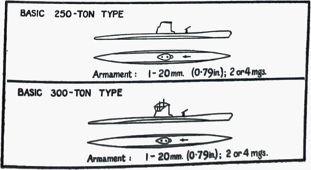
| (iv) Type II (A, B, C, D). | ||||||||||||||||||||||||||||||||||||||||||||||||||||||||||||||||||||||||||||||||||||||||||||||||||||||
| (a) Types IIA and IIB are standard 250-tonners. Types IIC and IID are 300-tonners, embodying slight improvements on the 250-ton design. These 4 types were withdrawn from operation early in 1940 and recommissioned as school boats. | ||||||||||||||||||||||||||||||||||||||||||||||||||||||||||||||||||||||||||||||||||||||||||||||||||||||
| Since the summer of 1942, some 250-tonners have been operating in the Black Sea, having been transported there overland and down the Danube; the remainder are still in commissioned as school boats and are known as "Nordsee Enten" (North Sea Ducks). | ||||||||||||||||||||||||||||||||||||||||||||||||||||||||||||||||||||||||||||||||||||||||||||||||||||||
| (b) Specifications (B2). | ||||||||||||||||||||||||||||||||||||||||||||||||||||||||||||||||||||||||||||||||||||||||||||||||||||||
|
||||||||||||||||||||||||||||||||||||||||||||||||||||||||||||||||||||||||||||||||||||||||||||||||||||||
 |
||||||||||||||||||||||||||||||||||||||||||||||||||||||||||||||||||||||||||||||||||||||||||||||||||||||
8 |
||||||||||||||||||||||
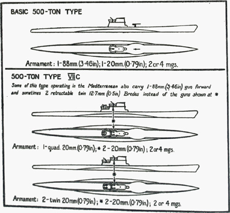
| (v) Type VII (B. C.) | ||||||||||||||||||||||
| (a) Type VII C is the most common type of operational U-Boat. It is mass assembled at a number of building yards. Type VII B is an earlier form, chiefly distinguished by its lack of quick diving tanks. | ||||||||||||||||||||||
| (b) Specifications of Type VII C (fact). | ||||||||||||||||||||||
| Standard Tonnage 500 | ||||||||||||||||||||||
| Length overall 220' | ||||||||||||||||||||||
| Beam maximum 20' | ||||||||||||||||||||||
| Diameter of pressure hull 15.4' | ||||||||||||||||||||||
| Length " " 144' | ||||||||||||||||||||||
| Draught 15.6' | ||||||||||||||||||||||
| Engines, two MAN or GW, 6 cylinders 1,400 H.P. each | ||||||||||||||||||||||
| Motors, two B.B.C., Siemens or A.E.G., 500 H.P. each | ||||||||||||||||||||||
| Speed: Maximum surfaced 18 knots | ||||||||||||||||||||||
| " submerged 7.4 knots | ||||||||||||||||||||||
| Endurance: 11,000 miles at 10 knots | ||||||||||||||||||||||
| Fuel: 128 tons | ||||||||||||||||||||||
| Torpedo tubes: 4 bow, 1 stern | ||||||||||||||||||||||
| Torpedoes: maximum of 14 | ||||||||||||||||||||||
| Average complement: 47-52 | ||||||||||||||||||||||
| Capacity: | ||||||||||||||||||||||
|
||||||||||||||||||||||
| Stern buoyancy tank 4.28 m3 | ||||||||||||||||||||||
| Bow " " 8.00 m3 | ||||||||||||||||||||||
 |
||||||||||||||||||||||
9 |
||||||||||||||||||||||||||||||||||||||||||||
| (vi) Type VII C 42. | ||||||||||||||||||||||||||||||||||||||||||||
|
||||||||||||||||||||||||||||||||||||||||||||
| Note: There is no evidence that this type has yet been serially produced or in operation. | ||||||||||||||||||||||||||||||||||||||||||||
| (vii) Type VII D. | ||||||||||||||||||||||||||||||||||||||||||||
| (a) A 500-ton minelayer, similar to type VII C but slightly longer with a raised and widened portion abaft the conning tower. There are five mine-shafts in a fore and aft line abaft the conning tower extending to the galley hatch. Each can take 3 mines. (B1). | ||||||||||||||||||||||||||||||||||||||||||||
| (b) Specifications (B2). | ||||||||||||||||||||||||||||||||||||||||||||
|
||||||||||||||||||||||||||||||||||||||||||||
10 |
||
| (viii) Type VII F. | ||
| (a) About four medium sized Torpedo Supply U-Boats have been built. They were originally intended to supply torpedoes to U-Boats in operational groups. Owing to the changed situation the intention was abandoned. This type is now used for the transport of torpedoes to bases which cannot be supplied by land, sea or air (i.e. Far East). Type VII F boats are similar to type VII C but with wider saddle tanks and can also be used offensively. The conning tower is further forward with a raised casing about 30 ft. long behind it. Upper deck rails for moving torpedoes, as fitted to 740-tonners, are carried. | ||
| (b) Specifications (B2). | ||
| Standard Tonnage: 500 | ||
| Actual Tonnage: 1,100/1,300 | ||
| Length overall: Approximately 255' | ||
| Beam maximum: 26' | ||
| Propulsion: As for type VII C | ||
| Endurance: About 20,000 miles at 10 knots. | ||
| Fuel: 280-300 tons. | ||
| Torpedo tubes: 4 bow - 1 stern | ||
| *Torpedoes: 44 | ||
| Complement: 47-52 | ||
| (c) Some type VII D minelayers may have had their mine shafts removed and been converted to type VII F, by utilising the shaft apace for torpedo stowage. (B3) | ||
| (d) Type VII F U-Boats are sluggish to handle, have poor sea-keeping qualities and are reported to vibrate badly at 16 knots. (B3) | ||
| * Torpedoes: A maximum of 44 can be carried. | ||
| (a) Up to 22 in the special compartment between the control room and P.O.'s mess abaft it. | ||
| (b) U- to 10 upper deck containers can be carried. | ||
| (c) Remainder as for normal Type VII C. | ||
11 |
||||||||||||||||||||||||||||||||||||||||||||||||||||||||||||||||||||||||||||||||||||||||||||||||||||||||||||||||||||||||||||||||||||||
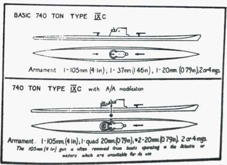
| (ix) Type IX C. | ||||||||||||||||||||||||||||||||||||||||||||||||||||||||||||||||||||||||||||||||||||||||||||||||||||||||||||||||||||||||||||||||||||||
| (a) A 740-ton U-boat, the most common operational type after the VII C. They usually operate further afield than 500-tonners, and are referred to in the German Navy as "See Kuhe" (Sea Cows); some boats of this type are operating from Penang (B2). | ||||||||||||||||||||||||||||||||||||||||||||||||||||||||||||||||||||||||||||||||||||||||||||||||||||||||||||||||||||||||||||||||||||||
| (b) Specifications (b2). | ||||||||||||||||||||||||||||||||||||||||||||||||||||||||||||||||||||||||||||||||||||||||||||||||||||||||||||||||||||||||||||||||||||||
|
||||||||||||||||||||||||||||||||||||||||||||||||||||||||||||||||||||||||||||||||||||||||||||||||||||||||||||||||||||||||||||||||||||||
 |
||||||||||||||||||||||||||||||||||||||||||||||||||||||||||||||||||||||||||||||||||||||||||||||||||||||||||||||||||||||||||||||||||||||
| (x) Type IX D (B3). | ||||||||||||||||||||||||||||||||||||||||||||||||||||||||||||||||||||||||||||||||||||||||||||||||||||||||||||||||||||||||||||||||||||||
| (a) A 740-ton minelaying U-boat similar to type IX C, fitted with 6 shafts in two parallel rows of 3 abaft the conning tower, each containing 3 mines. | ||||||||||||||||||||||||||||||||||||||||||||||||||||||||||||||||||||||||||||||||||||||||||||||||||||||||||||||||||||||||||||||||||||||
| (b) Specifications (C3). | ||||||||||||||||||||||||||||||||||||||||||||||||||||||||||||||||||||||||||||||||||||||||||||||||||||||||||||||||||||||||||||||||||||||
|
||||||||||||||||||||||||||||||||||||||||||||||||||||||||||||||||||||||||||||||||||||||||||||||||||||||||||||||||||||||||||||||||||||||
12 |
||
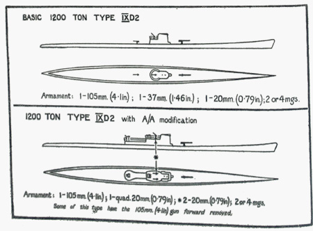
| (xi) Type IX D2. | ||
| (a) A 1,200 ton operational boat of better seagoing qualities than 500 and 740-ton types. Usually commanded by experienced C.O.'s of proved fighting spirit. Have been used for distant operations in S. Atlantic, Indian Ocean and Cape of Good Hope area. Known as "U-Kreuzer" (U-Cruisers) or "Ubersee Kühe" (super or overseas cows). | ||
| (b) Specifications (B2). | ||
| Standard tonnage: 1,200 | ||
| Length overall: 290' | ||
| Beam maximum: 20' | ||
| Draught: 16' | ||
| Engines: 2 MAN 9 cylinder of 2,000 H.P. each and a 2 MWM 6 cylinder of 500 H.P. each. | ||
| Motors: 2 over 500 H.P. each | ||
| Speed: surface 18 knots | ||
| submerged 6 " | ||
| Endurance: 25.000 miles at 10 knots | ||
| Fuel: 550 m3 (475 tons) | ||
| Torpedo Tubes: 4 bow and 2 stern | ||
| Torpedoes: 27 | ||
| Complement: 55-60 | ||
| (c) Tank Capacities. | ||
| Fuel oil tank 1a - port and starboard - each 22 m3 | ||
| " " " 2a " " " " 24 m3 | ||
| Main ballast and fuel oil tank No. 2 - port and starboard - each 28 m3 | ||
| " " " " " " No. 3 " " " " 28 m3 | ||
| " " " " " " No. 4 " " " " 31 m3 | ||
| Regulating and reserve fuel oil tank " " " " 18 m3 | ||
| Main ballast and reserve fuel oil tank No. 6 - port and starboard - each 27 m3 | ||
| " " " " " " " No. 7 " " " " 24 m3 | ||
| Fuel oil tank 3a - port and starboard - each 22 m3 | ||
| " " " 4a " " " " 24 m3 | ||
Lubricating oil supply tank No. 1-5', 6 m3 |
||
| " " " " No. 2-4', 5 m3 | ||
| " " " " No. 3-4', 5 m3 | ||
| " " " " No. 4-3', 6 m3 | ||
| " " " " No. 5-3', 3 m3 | ||
| Dirty lubricating oil tank 1 m3 | ||
| Lubricating oil collecting tanks - port and starboard - each 0.9 m3 | ||
| Auxiliary motor oil collecting tanks - port and starboard - each 0.8 m3 | ||
| Diesel fuel oil gravity tank 1.8 m3 | ||
| Junkers compressor fuel oil tank 0.5 m3 | ||
| Lubricating oil tank for superchargers 0.06 m3 | ||
| Torpedo compensating tank No. 1 2.5 m3 | ||
| " " " No. 2 2.5 m3 | ||
| " " " No. 3 5 m3 | ||
| " " " No. 4 5 m3 | ||
| After trimming tank 4.5 m3 | ||
| Forward " " 4.5 m3 | ||
| (d) Boats of this type can carry a rotor kite (see Chapter III) (B2). | ||
| (e) Two of there U-Boats were fitted with 6 Mercedes E-boat engines (see Chapter II) giving a surface speed of 24 knots and a correspondingly shorter endurance (B2). This was not satisfactory as the high revolutions involved excessive maintenance. The two experimental prototypes were Type 1 x D2 (B2). | ||
 |
||
13 |
||||||||||||||||||||||||||||||||||
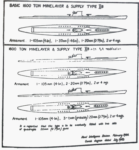
| (xii) Type X B (B2). | ||||||||||||||||||||||||||||||||||
| (a) A 1,600-ton minelaying supply U-boat. Although primarily a minelayer, is also used to supply small quantities of fuel when required. There are 6 free flooding shafts forward of conning tower each containing 3 mines, and 12 free flooding shafts each side amidships each containing 2 mines. Surface laying speed varies between 8 and 12 knots and submerged laying speed is between 3 and 4 knots at a depth of 34-40 metres (100-130 ft.). Mines have been laid about 400 metres (1,300 ft.) apart. | ||||||||||||||||||||||||||||||||||
| (b) Specifications (B1) | ||||||||||||||||||||||||||||||||||
|
||||||||||||||||||||||||||||||||||
 |
||||||||||||||||||||||||||||||||||
14 |
||
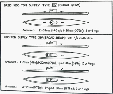
| (viii) Type XIV. | ||
| (a) A 1,600-ton supply U-Boat which supplies offensive U-Boats with fuel, provisions, spare parts and occasionally torpedoes at sea, to permit them to extend their sphere of operations. From 20-30 m3 (17-34 tons) is average amount of fuel supplied in N. Atlantic, and 50-100 m3 (42-85 tons) in the S. Atlantic. Type XIV U-Boats are based on the VII C pressure hull but have large external tanks. For refuelling procedure see Chapter XI. | ||
| (b) Specifications (B2). | ||
| Tonnage: 1,600 | ||
| Length: 220' | ||
| Beam, maximum: 26' | ||
| Diameter of pressure hull: 16.4' | ||
| Draught: 21.3' | ||
| Motors: B.B.C., Siemens or A.E.G., 500 H.P. each | ||
| Speed: maximum surfaced 13-14 knots | ||
| maximum submerged 6 " | ||
| Endurance: 10,000 miles at 10 knots | ||
| Fuel: 727.5 m3 (618 tons), of which 130 m3 (110 tons) is for own use | ||
| Torpedo tubes: None | ||
| Torpedoes: 4 can be carried in upper deck container | ||
| Provisions: Approximately 40 tons carried | ||
| Workshop to effect running repairs | ||
| Compensating tank: 54 m3 | ||
| Oxygen: 750 litres at 150 Atms | ||
| Complement: 60-65 | ||
 |
||
15 |
||
| (xiv) Recent U-boat Building Developments. | ||
| The information given below is summarized from reports up to June 1944. Details are provisional and subject to correction in the light of later information. | ||
| (i) Normal Operational Types of U-Boat. Since February, 1944, no U-boats of normal operational type have been laid down in German building yards, and in some cases hulls of such types laid down since autumn, 1943, have been taken up or permanently launched. | ||
| (ii) Experimental and New Types of U-boat. Since February, 1944, the Germans have gone ahead with the serial production, so far in limited numbers of two types of U-boat, better fitted than the older types to escape Allied A/S methods: | ||
| (a) 250 ft. prefabricated type. An ocean-going U-boat rapidly assembled on the slips from sections prefabricated elsewhere, which probably has a higher underwater speed and endurance than normal; Type XXI; standard tonnage 1200 (B3). | ||
| (b) 110 ft. small U-boat. A short-range boat which probably has higher underwater speed than normal. | ||
| Note: By June, 1944, a limited number of both types had been launched, but none had begun operational service. | ||
| (c) Experimental types. Since the summer of 1943 the Germans have intensively experimented with various kinds of small U-boats and submersible assault craft; a "human-torpedo" improvised from two normal 21" electric torpedoes has been used in the Mediterranean. | ||
| (iii) U-Boat Propulsion. The new types referred to in para. (i) (a) and (b) above are believed to have electric propulsion submerged. | ||
| The Germans have intensively sought to develop some form of closed-cycle engine for underwater propulsion of U-boats. So far German designers have apparently not yet perfected this system; Italian U-boat designers are believed further advanced, and the Germans may seek to apply Italian experience to their own practice. | ||
| (iv) Anti-Detection and Protective Devices. Since autumn, 1943, the Germans have experimented and exercised with new devices to counter allied radar, asdics, hydrophones and depth-charges; their success is not yet known. | ||
16 |
||||||||||||||||||||||||||||||||||||||||||||||||||||||||||||||||||||||||||||||||||||||||||||||||||||||||||||||||||||||||||||||||||
CHAPTER II |
||||||||||||||||||||||||||||||||||||||||||||||||||||||||||||||||||||||||||||||||||||||||||||||||||||||||||||||||||||||||||||||||||
U-BOAT GUN ARMAMENT |
||||||||||||||||||||||||||||||||||||||||||||||||||||||||||||||||||||||||||||||||||||||||||||||||||||||||||||||||||||||||||||||||||
| (i) The following types of gun armament have been and are fitted in U-Boats (B2). | ||||||||||||||||||||||||||||||||||||||||||||||||||||||||||||||||||||||||||||||||||||||||||||||||||||||||||||||||||||||||||||||||||
|
||||||||||||||||||||||||||||||||||||||||||||||||||||||||||||||||||||||||||||||||||||||||||||||||||||||||||||||||||||||||||||||||||
| Notes: (i) The maximum angle of elevation for the 105 mm. gun is 50-60, but a number have been adapted for A.A. work by adding a small geared wheel of about 10 cm. diameter between the normal elevation gear and the gun barrel. This is claimed to increase the angle of elevation to 80-85. (C3) | ||||||||||||||||||||||||||||||||||||||||||||||||||||||||||||||||||||||||||||||||||||||||||||||||||||||||||||||||||||||||||||||||||
| (ii) (a) This 37 mm. is fully automatic; the 37 mm. which was fitted to some U-Boats earlier in the war was breech loading and had a much slower rate of fire. The new 37 mm. has since late 1943 been replacing the quadruple 20 mm. as a standard fitting (fact) but there are indications that it may itself now be removed because of frequent jamming under marine conditions. (B2) | ||||||||||||||||||||||||||||||||||||||||||||||||||||||||||||||||||||||||||||||||||||||||||||||||||||||||||||||||||||||||||||||||||
| (b) Ammunition is in clips of five. | ||||||||||||||||||||||||||||||||||||||||||||||||||||||||||||||||||||||||||||||||||||||||||||||||||||||||||||||||||||||||||||||||||
| (iii) (a) The quadruple 20 mm. consists of four normal 20 mm. guns mounted in pairs side by side. Trigger control is such that any two diagonal barrels may be fired simultaneously by pressing ont of the two triggers. This weapon has been found clumsy to handle since it is laid and trained by one man working two handwheels, as well as difficult to train during an aircraft's run-up, and especially during a breakaway. Consequently it has been partially replaced by (a) twin 20 mm. guns, and (b) a fully automatic 37 mm. (See also Note (ii) (a).) | ||||||||||||||||||||||||||||||||||||||||||||||||||||||||||||||||||||||||||||||||||||||||||||||||||||||||||||||||||||||||||||||||||
| An improved better balanced quadruple 20 mm. was reported to be fitted to Med. U-Boats February, 1944, C2) | ||||||||||||||||||||||||||||||||||||||||||||||||||||||||||||||||||||||||||||||||||||||||||||||||||||||||||||||||||||||||||||||||||
| (b) 20 mm. ammunition is in clips of 20 (fact). | ||||||||||||||||||||||||||||||||||||||||||||||||||||||||||||||||||||||||||||||||||||||||||||||||||||||||||||||||||||||||||||||||||
| (c) Both the C.30 and C.38 are 20 mm. weapons. The C.38 was constructed in 1938 and has the rate of fire quoted. The C.30 has a rate of fire about 20 per cent. lower and is not often encountered now; it is the 1930 model (fact). | ||||||||||||||||||||||||||||||||||||||||||||||||||||||||||||||||||||||||||||||||||||||||||||||||||||||||||||||||||||||||||||||||||
| (iv) The M.G.(C/34) and M.G.15 are still met although generally replaced by the M.G.81 (either in the single-barreled or twin-barreled version). The M.G.81 is not entirely satisfactory under marine conditions in spite of its advantageously high rate of fire (B2). | ||||||||||||||||||||||||||||||||||||||||||||||||||||||||||||||||||||||||||||||||||||||||||||||||||||||||||||||||||||||||||||||||||
| (v) The 12.7 mm. (Breda) guns have also sometimes been mounted on the bandstand of Mediterranean U-boats and the fitting of a 40 mm. gun in the same position has also been reported from Bay of Biscay ports. Available data is noted in Table 2 (B3). | ||||||||||||||||||||||||||||||||||||||||||||||||||||||||||||||||||||||||||||||||||||||||||||||||||||||||||||||||||||||||||||||||||
| (ii) Arrangements of Armament. | ||||||||||||||||||||||||||||||||||||||||||||||||||||||||||||||||||||||||||||||||||||||||||||||||||||||||||||||||||||||||||||||||||
| From the outbreak of war in 1939 until the late spring of 1943, gun armament in Atlantic U-Boats hardly varied. In 1943 the U-Boat felt compelled to increase the fire power of her A.A. armament even at the expense of discarding the heavier 88 mm. and 105 mm. guns forward of the bridge (fact). (See Table 1, column 3). | ||||||||||||||||||||||||||||||||||||||||||||||||||||||||||||||||||||||||||||||||||||||||||||||||||||||||||||||||||||||||||||||||||
17 |
||||||||||||||||||||||||||||||||||||||||||||||||||||||||||||||||||||||||||||||||||||||||||||||||||||||||||||||
| The change in the armament arrangement since 1943 may be seen by comparing the left hand (1939-1943) with the right hand (1943 onwards) columns which follow: | ||||||||||||||||||||||||||||||||||||||||||||||||||||||||||||||||||||||||||||||||||||||||||||||||||||||||||||||
TABLE I. |
||||||||||||||||||||||||||||||||||||||||||||||||||||||||||||||||||||||||||||||||||||||||||||||||||||||||||||||
|
||||||||||||||||||||||||||||||||||||||||||||||||||||||||||||||||||||||||||||||||||||||||||||||||||||||||||||||
| (i) A later type of additional bandstand is fitted in some Blohm & Voss boats 3 feet abaft the normal bandstand. | ||||||||||||||||||||||||||||||||||||||||||||||||||||||||||||||||||||||||||||||||||||||||||||||||||||||||||||||
| They are connected to each other by a sloping catwalk with raised sides which also act as an ammunition chute. | ||||||||||||||||||||||||||||||||||||||||||||||||||||||||||||||||||||||||||||||||||||||||||||||||||||||||||||||
| (ii) The 20 mm. guns are now generally fitted with a mounting about 18" high, and at least two U-boats (U.607, sunk 13th July, 1943, and U.536, sunk 20th October, 1943) had bandstand decks about 18" higher than normal, thus permitting forward fire even against aircraft flying low from dead ahead. It is likely, therefore, that aircraft can no longer rely on the blind area of 18 degrees on either bow at heights of 50 feet and below. | ||||||||||||||||||||||||||||||||||||||||||||||||||||||||||||||||||||||||||||||||||||||||||||||||||||||||||||||
| 35787 B | ||||||||||||||||||||||||||||||||||||||||||||||||||||||||||||||||||||||||||||||||||||||||||||||||||||||||||||||
18 |
|||||||||||||||||||||||||||||||||||||||||||||||||||||||||||||||||||||||||||||||||||||||||||||||||||||||||||||||||||||||||||||||||||||||||||||||||||||||||||||
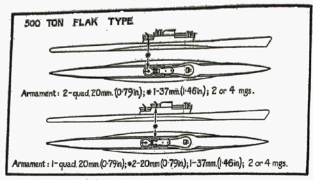
| (iii) Flak U-Boats. | |||||||||||||||||||||||||||||||||||||||||||||||||||||||||||||||||||||||||||||||||||||||||||||||||||||||||||||||||||||||||||||||||||||||||||||||||||||||||||||
| Some 500-ton U-Boats have been converted in French Atlantic bases for use as "Flak" U-boats. In late summer, 1943, six were being converted at Brest. The following is the standard armament, but other variations are possible: (B3) | |||||||||||||||||||||||||||||||||||||||||||||||||||||||||||||||||||||||||||||||||||||||||||||||||||||||||||||||||||||||||||||||||||||||||||||||||||||||||||||
 |
|||||||||||||||||||||||||||||||||||||||||||||||||||||||||||||||||||||||||||||||||||||||||||||||||||||||||||||||||||||||||||||||||||||||||||||||||||||||||||||
| The only torpedoes carried are those in the tubes, a large amount of ammunition being carried in place of spare torpedoes. | |||||||||||||||||||||||||||||||||||||||||||||||||||||||||||||||||||||||||||||||||||||||||||||||||||||||||||||||||||||||||||||||||||||||||||||||||||||||||||||
| These U-boats are probably chiefly for use in Bay of Biscay, either as escorts or on patrol. They have been encountered on a very few occasions, when they have by no means had it all their own way. | |||||||||||||||||||||||||||||||||||||||||||||||||||||||||||||||||||||||||||||||||||||||||||||||||||||||||||||||||||||||||||||||||||||||||||||||||||||||||||||
| (iv) Performance and Ammunition. | |||||||||||||||||||||||||||||||||||||||||||||||||||||||||||||||||||||||||||||||||||||||||||||||||||||||||||||||||||||||||||||||||||||||||||||||||||||||||||||
| Available information is summarised below. | |||||||||||||||||||||||||||||||||||||||||||||||||||||||||||||||||||||||||||||||||||||||||||||||||||||||||||||||||||||||||||||||||||||||||||||||||||||||||||||
| Note: The practical rate of fire has been sub-divided into "Rate of Fire during one run up by Aircraft" in Table 2, column 3 (b). Theoretical rate of fire is ignored in this summary. | |||||||||||||||||||||||||||||||||||||||||||||||||||||||||||||||||||||||||||||||||||||||||||||||||||||||||||||||||||||||||||||||||||||||||||||||||||||||||||||
TABLE 2. |
|||||||||||||||||||||||||||||||||||||||||||||||||||||||||||||||||||||||||||||||||||||||||||||||||||||||||||||||||||||||||||||||||||||||||||||||||||||||||||||
|
|||||||||||||||||||||||||||||||||||||||||||||||||||||||||||||||||||||||||||||||||||||||||||||||||||||||||||||||||||||||||||||||||||||||||||||||||||||||||||||
19 |
||
| Tracer and Incendiary. The 20 mm. and 37 mm. ammunition only differ from each other in calibre and range. Up to August 1943 tracer plugs were fitted to H.E. Some H.E./A.P. are now fitted with tracer (B3). It is claimed that all tracer ammunition will in future be tracer/incendiary. A new type of 37 mm. phosphorous incendiary ammunition and the introduction of 20 mm. incendiary is also reported. No details are available. | ||
| (v) Armour. | ||
| U-boats with the new armament have also been fitted with armour on the forward part of the bridge. This plate is probably of 20 mm. thickness. Gun shields of 10-15 mm. armour give complete cover to the quadruple gun crews who do not, however, feel really protected from .50 calibre fire. The fully automatic 37 mm. gun, when fitted, is also fully shielded by armour of 10-15 mm. thickness. | ||
| In addition bridges have been fitted with armoured doors which, when closed, offer protection against fire from astern. They were being removed from some U-boats beginning of 1944 as they impeded diving (B3). | ||
| (vi) Rocket Projectors. | ||
| (a) As a counter to heavier Allied attacks rocket projectors are now being fitted to U-boats in the Biscay ports (C3). | ||
| (b) The projectiles have a calibre of 8-1- cms. and are charged with liquid air (C3). Some boats are being fitted with single or double projectors, other with batteries of 4-6. They have been reported on either side of the conning tower or abaft it and round the bandstand guard rails (C3). Firing is electric (C3). | ||
| (vii) Triple Bandstands. | ||
| An additional bandstand has been fitted to certain operational U-boats before the bridge (B2) end of 1943. Experiments with a second bandstand abaft the bridge Reported February 1944 (C3). | ||
| (viii) 30 mm. gun. | ||
| Reports have been received that a 30 mm. gun is being fitted to U-boats (B3). It is claimed to be the mean between the heavier and slower firing 37 mm. and the light and quick-firing 20 mm. gun. | ||
| 35787 B 2 | ||
20 |
|||||||||||||||||||||||||||||||||||||||||||||||||||||||||||||||||||||||||||||||||||
CHAPTER III |
|||||||||||||||||||||||||||||||||||||||||||||||||||||||||||||||||||||||||||||||||||
STANDARD U-BOAT EQUIPMENT |
|||||||||||||||||||||||||||||||||||||||||||||||||||||||||||||||||||||||||||||||||||
SECTION I: PROPULSION |
|||||||||||||||||||||||||||||||||||||||||||||||||||||||||||||||||||||||||||||||||||
| For full technical details of German VII C 500-ton U-Boat, U-570 (H.M.S. "GRAPH") see C.B. 4318. | |||||||||||||||||||||||||||||||||||||||||||||||||||||||||||||||||||||||||||||||||||
| (i) Diesel Engines. | |||||||||||||||||||||||||||||||||||||||||||||||||||||||||||||||||||||||||||||||||||
| (a) Types and Manufacturers. The main propulsion of German U-Boats is based on two sizes of engine, a 6-cylinder 1,400 h.p. supercharged Diesel and a 9-cylinder 2,200 h.p. supercharged Diesel. These have been almost entirely made or under licence from G.W. (Germania Werft) and M.A.N. (Maschinenfabrik Augsburg Nurnberg A.G.) although future Diesels for 500-tonners will be built only to G.W. designs partly because the engines are more rugged and better suited to the present standard of the German E.R.A., and partly because of spares problems. (B3). Up to the middle of 1943 the proportions of engines made to the various designs were G.W., 50 per cent.; M.A.N., 40 per cent. Wumag and others, 10 percent. M.W.M (MotorenWerke Mannheim A.G.) build 350 h.p. 6-cylinder engines for 250 and 300 ton U-boats. Wagen and Maschinenbau A.G. (Wumag) building G.W. engines under licence. (B2). | |||||||||||||||||||||||||||||||||||||||||||||||||||||||||||||||||||||||||||||||||||
|
|||||||||||||||||||||||||||||||||||||||||||||||||||||||||||||||||||||||||||||||||||
| During 1943 two 1,200-ton U-boats were fitted with 6 Mercedes-Benz MB-501 or 501A 20 cylinder E-boat engines of 2,000 h.p. each. These gave the boat a maximum surface speed of 24 knots. Maintenance problems were such that during the beginning of 1944 these were being replaced by 12-cylinder M.A.N. Diesels with the same dimensions as the familiar M.A.N. 9-cylinder type (B3). | |||||||||||||||||||||||||||||||||||||||||||||||||||||||||||||||||||||||||||||||||||
| (b) Superchargers. All Diesels are fitted with one of the following types of superchargers: | |||||||||||||||||||||||||||||||||||||||||||||||||||||||||||||||||||||||||||||||||||
| (i) Turbo-compressor driven through gearing (Turbinegebläse). | |||||||||||||||||||||||||||||||||||||||||||||||||||||||||||||||||||||||||||||||||||
| (ii) Turbo-compressor driven through exhaust gas turbine (Büchigrbläse). | |||||||||||||||||||||||||||||||||||||||||||||||||||||||||||||||||||||||||||||||||||
| (iii) Rootes blower driven through gearing (Kapselgebläse). | |||||||||||||||||||||||||||||||||||||||||||||||||||||||||||||||||||||||||||||||||||
| M.A.N. always fit Buchi. The type most commonly fitted to other Diesels is the Rootes blower type. All three types give a pressure of .2 to .3 atmospheres. (B2) | |||||||||||||||||||||||||||||||||||||||||||||||||||||||||||||||||||||||||||||||||||
| (c) Short bursts of high speed on surface. If the state of the batteries permits, speed can be increased about half a knot by running the electric motors and Diesels simultaneously. (Fact). | |||||||||||||||||||||||||||||||||||||||||||||||||||||||||||||||||||||||||||||||||||
| (d) Speeds when surfaced (on two Diesels in calm weather): | |||||||||||||||||||||||||||||||||||||||||||||||||||||||||||||||||||||||||||||||||||
|
|||||||||||||||||||||||||||||||||||||||||||||||||||||||||||||||||||||||||||||||||||
| (e) "Diesel-Electric" propulsion. Only one Diesel is run; it drives its own shaft and motor which, acting as a generator, supplies power to the motor on the other shaft. The electrically-driven shaft makes about half the revolutions obtained on the other. Economical Diesel-electric speed is about 6 knots. It has the advantage that the idle engine can be serviced, and that the single engine can run at its most efficient speed. (Fact) | |||||||||||||||||||||||||||||||||||||||||||||||||||||||||||||||||||||||||||||||||||
| (ii) Electric Motors. | |||||||||||||||||||||||||||||||||||||||||||||||||||||||||||||||||||||||||||||||||||
| (a) Manufacturers. The principal are Siemens, Allgemeine Elektrizitäts Gesellschaft (A.E.G.), Brown Boveri Compagnie (B.B.C.) (Fact) | |||||||||||||||||||||||||||||||||||||||||||||||||||||||||||||||||||||||||||||||||||
| (b) Details. Motors are double-commutator type. 250-tonners have two, each rated at 180 h.p., 500-tonners two, each rated at 500 h.p., and 740-tonners two, each rated at 750-h.p. The maximum rating for motors on 500-tonners is 280 r.p.m. at 720 amps. and 228 volts for half an hour. (Fact). | |||||||||||||||||||||||||||||||||||||||||||||||||||||||||||||||||||||||||||||||||||
| Radio Suppression. 2 x 3 micro-Farad condensors are fitted across each commutator. | |||||||||||||||||||||||||||||||||||||||||||||||||||||||||||||||||||||||||||||||||||
21 |
||||||||||||||||||||||||||||||||||||||||||||||||||||||||||||||||||||||||||
| (c) Speeds submerged: | ||||||||||||||||||||||||||||||||||||||||||||||||||||||||||||||||||||||||||
|
||||||||||||||||||||||||||||||||||||||||||||||||||||||||||||||||||||||||||
| Great stress is laid on finding the most silent running speed for each U-boat. It is generally about 90 r.p.m. and this "silent" speed is known as "Schleichfahrt". (Fact) | ||||||||||||||||||||||||||||||||||||||||||||||||||||||||||||||||||||||||||
| (iii) Switchboards. | ||||||||||||||||||||||||||||||||||||||||||||||||||||||||||||||||||||||||||
| Switchboards are generally made by or under licence of the manufacturers of the motors. Mention has been made of a new type of switchboard made by Siemens-Schuckert which has a remote control panel. | ||||||||||||||||||||||||||||||||||||||||||||||||||||||||||||||||||||||||||
| (iv) Batteries. | ||||||||||||||||||||||||||||||||||||||||||||||||||||||||||||||||||||||||||
| (a) Batteries are normally of the lead-acid type (fact) although experiments with nickel batteries have been reported. (C3). | ||||||||||||||||||||||||||||||||||||||||||||||||||||||||||||||||||||||||||
| (b) 500-tonners generally carry two units of 62 cells each with a total amp./hr. capacity of 11,000. The one and half hour discharge rate is 3,630. (Fact) | ||||||||||||||||||||||||||||||||||||||||||||||||||||||||||||||||||||||||||
| (c) 740-tonners are believed to carry similar batteries but with a total amp./hr. capacity of 15,000. (C3). | ||||||||||||||||||||||||||||||||||||||||||||||||||||||||||||||||||||||||||
| (d) 1,600-ton supply boats carry similar batteries with a total capacity of 13,000 amp./hr. (B2). | ||||||||||||||||||||||||||||||||||||||||||||||||||||||||||||||||||||||||||
| (e) Manufacturers include Hagen, and A.F.A. and types include M.L.A. 1000, M.L.A. 800, M.L.A. 44, 36 M.A.K. and 33 M.A.L. (Fact). | ||||||||||||||||||||||||||||||||||||||||||||||||||||||||||||||||||||||||||
| (f) Battery cells are fitted with rubber linings to prevent acid spilling in the event of cracking. (B2). | ||||||||||||||||||||||||||||||||||||||||||||||||||||||||||||||||||||||||||
| (g) Batteries are unspillable. (Fact). | ||||||||||||||||||||||||||||||||||||||||||||||||||||||||||||||||||||||||||
| (v) Schnorkel (Extensible Exhaust and Air-intake). | ||||||||||||||||||||||||||||||||||||||||||||||||||||||||||||||||||||||||||
| Some U-boats are fitted with a trunk known as Schnorkel enabling them to charge batteries at slow speed while at periscope depth. This trunk is about 30 cms. wide and 8 metres long and contains two tubes about 15 cms. in diameter; one the Diesel air-intake; the other an exhaust pipe. The open ends of the tube face aft covered by a mushroom-shaped cowl at the top of the trunk. The trunk is usually on the port side and when not in use lies flat on deck, the lower end against the forward part of the bridge. There is a watertight joint at the lower end of the trunk which connects through the pressure hull via the control room to the standard Diesel trunks. Erection when surfaced or at periscope depth is by oil pressure. When flat on deck both types are free-flooding, the intake being drained by a triple valve system. Self-sealing valves in the intake prevent the Diesels being flooded. (B2). | ||||||||||||||||||||||||||||||||||||||||||||||||||||||||||||||||||||||||||
| The top of the trunk has been fitted with a G.S.R. aerial capable of detecting radar on frequencies less than 400 Mc/s. | ||||||||||||||||||||||||||||||||||||||||||||||||||||||||||||||||||||||||||
| Schnorkel has been used in the Bay of Biscay and the Channel and is intended for use in areas where frequent A/S patrols and air cover are likely to be encountered. | ||||||||||||||||||||||||||||||||||||||||||||||||||||||||||||||||||||||||||
| Schnorkel may be used in seas up to 3-4. A 500-ton U-boat fitted with Schnorkel can probably: | ||||||||||||||||||||||||||||||||||||||||||||||||||||||||||||||||||||||||||
| (a) proceed at periscope depth at about 6 knots without charging batteries; | ||||||||||||||||||||||||||||||||||||||||||||||||||||||||||||||||||||||||||
| (b) proceed at about 4-5 knots while charging at a low rate; | ||||||||||||||||||||||||||||||||||||||||||||||||||||||||||||||||||||||||||
| (c) charge at a high rate while proceeding at very low speed. | ||||||||||||||||||||||||||||||||||||||||||||||||||||||||||||||||||||||||||
| An improved Schnorkel has been reported consisting of one single trunk as air intake, the exhaust gasses to eliminate tell-tale smoke being expelled underwater from the U-boat itself. The new "Schnörkel" is hydraulically operated from the control room like a periscope (B3). Automatic hydroplanes to assist depth keeping and speeds up to 6-7 knots are reported. (B3). | ||||||||||||||||||||||||||||||||||||||||||||||||||||||||||||||||||||||||||
| (vi) Single unit propulsion in U-boats (Einheitsantreib). | ||||||||||||||||||||||||||||||||||||||||||||||||||||||||||||||||||||||||||
| Many reports have been received of experiments designed to produce a U-boat driven by the same engine submerged and surfaced. The chief advantage would be a considerable saving in weight, particularly by the elimination of batteries, and a consequent increase in performance, especially submerged. | ||||||||||||||||||||||||||||||||||||||||||||||||||||||||||||||||||||||||||
| U-boats with this propulsion are still in the experimental stage, and appear mainly to be divided between underwater reciprocating engines and gas turbines. The theoretical possibilities are so numerous that no attempt has been made to classify them in this book. | ||||||||||||||||||||||||||||||||||||||||||||||||||||||||||||||||||||||||||
| 35787 B 3 | ||||||||||||||||||||||||||||||||||||||||||||||||||||||||||||||||||||||||||
22 |
||||||||||||||||||||||||||
SECTION II. GERMAN U-BOAT COMMUNICATIONS |
||||||||||||||||||||||||||
| (i) Anglo-German Equivalent Wave Ranges. | ||||||||||||||||||||||||||
| As the German nomenclature of wave ranges is different from that of the Allies (fact), it is given here for convenience: | ||||||||||||||||||||||||||
|
||||||||||||||||||||||||||
| "Ultrakurzwellen" are subdivided into: | ||||||||||||||||||||||||||
|
||||||||||||||||||||||||||
| (ii) W/T Equipment. | ||||||||||||||||||||||||||
| All U-boats carry the following or similar W/T gear: | ||||||||||||||||||||||||||
| (a) W/T Transmission. | ||||||||||||||||||||||||||
| (1) 1 Telefunken H/F transmitter 200 watt, frequency range 3.75 to 15 mc/s. S 406 S. | ||||||||||||||||||||||||||
| (2) 1 Telefunken M/F transmitter 150 watt, frequency range 300 to 600 kc/s. Spez. 2113 S. | ||||||||||||||||||||||||||
| (3) 1 Lorenz H/F transmitter 40 watt, frequency range 5 to 16.7 mc/s. 40 K 39 a. | ||||||||||||||||||||||||||
| (4) No R/T transmitter usually carried on operations. | ||||||||||||||||||||||||||
| (b) W/T Reception. | ||||||||||||||||||||||||||
| (1) 1 Telefunken H/F receiver, frequency range 1.5 to 25 mc/s. E 437 S. | ||||||||||||||||||||||||||
| (2) 1 Telefunken all-wave receiver, range 15 to 20,000 kc/s. E 381 S. | ||||||||||||||||||||||||||
| (3) 1 Telefunken broadcast receiver, covering usual broadcast short-long wave bands. Era 1012. | ||||||||||||||||||||||||||
| (4) 1 Radione broadcast receiver ditto. R2 or R3. | ||||||||||||||||||||||||||
| (5) The Radione receiver is used for recreational purposes, and programmes on it are played to the crew by means of 10 or so loudspeakers throughout the boat. The use of this set has been recently banned, as it is not proof against enemy D/F. | ||||||||||||||||||||||||||
| (6) Recently prisoners have mentioned a Lorenz H/F receiver called "Main", which has a frequency range of 3 to 20 mc/s. This receiver is said to be a superhet giving very good reception, and being proof against enemy D/F. This set replaces (b1) above. | ||||||||||||||||||||||||||
| (iii) Manufacturers. | ||||||||||||||||||||||||||
| Manufacturers of the above gear include (fact) Lorenz, Telefunken, Petersen, Radione, Kriegsmarine Werft (Kiel) and Philipps. | ||||||||||||||||||||||||||
| (iv) Arrangement of Sets. | ||||||||||||||||||||||||||
| (a) General. The position of boats communication equipment is much the same in all classes of boat. The majority of equipment goes into two cabins next to the control room. Cabin 1 is called the wireless room, and cabin 2 the hydrophone room, as it contains hydrophones as well as various pieces of W/T equipment. In 500-ton boats, cabin 1 has a floor area of 5' x 5', cabin 2 about 5' x 4'6". In larger boats a little more space is provided. | ||||||||||||||||||||||||||
| (b) Contents of Cabin 1. | ||||||||||||||||||||||||||
| (1) 150 Watt Telefunken M/F and 200 Watt Telefunken H/F transmitters. | ||||||||||||||||||||||||||
| (2) Telefunken H/F receiver. | ||||||||||||||||||||||||||
| (3) Sometimes Radione broadcast receiver. | ||||||||||||||||||||||||||
| (4) D/F receiver. | ||||||||||||||||||||||||||
| (5) S/T. | ||||||||||||||||||||||||||
| (6) G.S.R. receiver. | ||||||||||||||||||||||||||
| (c) Contents of Cabin 2. | ||||||||||||||||||||||||||
| (1) 40 Watt Lorenz H/F transmitter. | ||||||||||||||||||||||||||
| (2) Telefunken all-wave receiver. | ||||||||||||||||||||||||||
| (3) Telefunken broadcast receiver. | ||||||||||||||||||||||||||
| (4) Any "secret" experimental gear. | ||||||||||||||||||||||||||
| (d) Miscellaneous. | ||||||||||||||||||||||||||
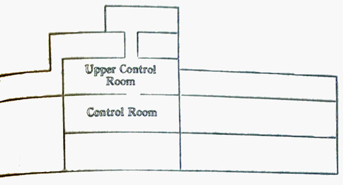
| (1) VH/F transceiver in upper control room | | ||||||||||||||||||||||||||
| (2) Radar transmitter in Asdic shaft } when carried | ||||||||||||||||||||||||||
| (3) Radar receiver in control room | | ||||||||||||||||||||||||||
| (4) Radione broadcast receiver in Captain's cabin or Officers' quarters. | ||||||||||||||||||||||||||
23 |
||||
| (e) Diagram | ||||
|
||||
 |
||||
| Plan of Main Deck | 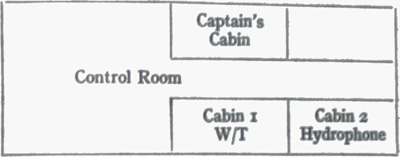 |
|||
| (v) Operational Performance. | ||||
| (a) H/F-W/T sets are primarily to enable U-boats to keep in touch with Control even when in distant waters. The Telefunken 200 Watt H/F transmitter, S 406 S, is normally used, the Lorenz 40 Watt being kept in reserve. The latter, with its higher frequency coverage, is sometimes more suitable. | ||||
| Receivers Telefunken E 437 S of "Main", when fitted, are used for the reception of H/F transmissions from control. The Telefunken all-wave receiver E 381 S is available in case of breakdown. The above equipment appears adequate and maintenance presents no difficulty. (B2) | ||||
| (b) VL/F. Enables U-boats to receive instructions and situation reports when proceeding at periscope depth through danger areas. For submerged reception the D/F loop and the VL/F band of the D/F receiver are used. For normal reception there may be between 5-10 ft. of water above the actual D/F loop. When "Goliath", a 1,000 kilowatt V/LF transmitter is operating, there may be between 15-20 ft. of water above the loop in both North and South Atlantic. (B2) The Germans attach great importance to VL/F. | ||||
| (c) All important reports received by Control from U-boats and operational instructions from Admiral U-boats are sent out on both H/F and VL/F broadcasts (fact). | ||||
| (vi) Intercommunication between U-boats. | ||||
| (a) Direct intercommunication between U-boats is rare; U-boats listen out for H/F transmissions from other U-boats to Control. When, for instance, a pack of U-boats are operating against a convoy, co-operation between boats is ensured by making them keep watch on a convoy wave on their H/F receivers, and make their reports on the same wave. These reports are re-broadcast by control so that all boats will receive them, whether they have managed to intercept the originator's report or not. If one of the boats detailed for the task is unable to find the convoy, it will signal Control requesting M/F beacon signals from a shadower, and Control will detail a boat in contact to make the necessary signals. A similar is adopted if a boat is finding difficulty in making a rendezvous with a supply boat. (B2) | ||||
| (b) Funkschlüsselgespräch. There is an authorised form of U-boat communication known as Funkschlüsselgespräch, consisting of direct inter-communication by W/T in cypher on H/F. Few U-boats have in practice used this type of communication. (B2) | ||||
| (c) M/F Beacon Signals. The Telefunken M/F transmitter 2113 1 S has a range of 50-100 miles, and is only used in conjunction with one of the jumping wire aerials for making beacon signals. It is not very satisfactory (B2). Reception is by the D/F loop and M/F band of the Telefunken D/F receiver E 539 S. | ||||
| (d) D/F. Telefunken D/F receiver covering two frequency bands 15 to 33 kc/s (VL/F) and 75-1,200 kc/s (H/F), type T31 Lä 38. In Autumn 1943 a D/F set has been fitted to some U-boats to enable them to take bearings on convoy R/T, covering at least the lower half of the H/F band (B2). Made by Lorenz. (C3) | ||||
| (e) S/T. Most U-boats carry S/T consisting of a transmitter and receiver normally used during trials. It is easily detached and only rarely used operationally. It has a range of about 10 miles, working on a sonic frequency of about 3.5 kc/s. (B2) | ||||
| 35787 B 4 | ||||
24 |
||||||||||||||||||
| (f) VH/F. The VH/F set carried by U-Boats is a Lorenz 1 Watt transceiver type Lo 1 U.K. 35 with a frequency of 41.55-45.75 mc/s. The range is about 10 miles and the set is usually but not always removed after Baltic trials, before U-boats become operational. (B2) | ||||||||||||||||||
| (g) V.S. Owing to the removal of VH/F communication sets, short range signaling has to be by V/S. An Aldis type signaling lamp, Scheinwerfer E.S. W.20 is used. (C3) | ||||||||||||||||||
| (h) Infra-Red. It is possible that the Germans are fitting in U-Boats an infra-red signaling device known as Seehund, consisting of an infra-red signaling unit and suitable search glasses. These could be used for station keeping, signaling or recognition. (C2) | ||||||||||||||||||
| (vii) Aerials. | ||||||||||||||||||
| (a) W/T. (i) Jumping wire aerials are carried, one usually forward of the bridge for normal transmission of H/F and M/F, and one or two aft of the bridge to the stern. The forward aerial is about 15 yards, the after sections about 18 yards in 500-ton boats. By means of an aerial exchange any of the jumping wire aerials can be connected to any transmitter or receiver. | ||||||||||||||||||
| (ii) An extensible rod antenna for transmission and reception of H/F is also occasionally fitted. It is mounted on the port side of the bridge, and, when fully extended, stands about 20' above the conning tower (fact). No details are available as to its insulation. Its performance is poor, and, as a Radar mattress displaces it, its fitting may well be discontinued. (B2) | ||||||||||||||||||
| (b) D/F. A loop antenna is provided, about 2'6" in diameter, and about 2' clear of the bridge casing when fully extended. It is fitted on the starboard side of the bridge and is retractable under cover of the bridge casing. This aerial is used, in conjunction with the D/F receiver, for bearing indication on M/F, and for reception of VL/F. (Fact) | ||||||||||||||||||
| (c) VH/F. A rod antenna is used, about 4' high, on the port side of the conning tower. It is presumably dismantles, when the set is removed before operational patrol. (B2) | ||||||||||||||||||
| (viii) Manning. | ||||||||||||||||||
| A W/T complement of 2 P.O. Tels. and 2 Tels. is general throughout the U-Boat service. | ||||||||||||||||||
| The division into watches is three day watches, lasting four hours each from 0800 until 2000, and two night watches, lasting six hours each from 2000 until 0800, with one P.O. and one Tel. on together in each watch. | ||||||||||||||||||
| On the surface the U-Boat is watched continuously on the H/R receiver. The junior operator will usually help the senior in watching the set or in doing the cyphering. | ||||||||||||||||||
| In danger zones, such as the Bay of Biscay, or near a convoy, the G.S.R. (see Section IV) is manned continuously. Other ratings, usually S.T.s, are detailed from the crew to make up the G.S.R. complement, as they must relieve each other on the instrument every hour. If anything which may be enemy location is picked up, it is immediately brought to the attention of the P.O. Tel. | ||||||||||||||||||
| Additional burdens during convoy attacks are those of manning the M/F D/F to take bearings on beacon signals, and of manning the Radar set if required. | ||||||||||||||||||
| When submerged, watch is kept on the U-boat VL/F transmissions from Control by means of the D/F loop aerial and D/F receiver. | ||||||||||||||||||
| In addition, the P.O. Tel. of the watch is responsible for manning the hydrophones. | ||||||||||||||||||
| (ix) Interception of Allied Communications | ||||||||||||||||||
| The D/F set in some U-boats enables bearings on convoy R/T to be taken. | ||||||||||||||||||
| A few U-boats carry specialists carefully trained in the interception of Allied communications. This is an experimental procedure, not as yet widely used. (B3) | ||||||||||||||||||
| In this connection the following technical equipment has been mentioned: | ||||||||||||||||||
| (a) Telefunken R/T receiver: Covers a very wide frequency range in five bands (B3) | ||||||||||||||||||
|
||||||||||||||||||
| (b) Lorenz D/F receiver, with frequency bands the same as for Telefunken R/T receiver, arranged in the same order. (Note: It is unlikely that bearings can be taken throughout the range). | ||||||||||||||||||
| Bearings are taken on convoy R/T, and convoy R/T traffic studied. The existence of "Hedgehog" was discovered by this means. Aircraft-ship R/T traffic is also watched, and prisoners claim that this enables then to estimate the number of aircraft associated with a convoy. | ||||||||||||||||||
| (x) Trend of Development. | ||||||||||||||||||
| There is little indication of any change in U-Boat W/T equipment. | ||||||||||||||||||
| The "Main" H/F receiver may be more widely fitted, as its performance is said to be very good. | ||||||||||||||||||
| The use of a D/F receiver capable of taking bearings on convoy R/T is likely to become general. | ||||||||||||||||||
| Increased interception activity is possible on the part of boats carrying specialist operators. | ||||||||||||||||||
| It is unlikely that VH/F will be reintroduced for convoy operations or that the use of S/T will be increased. | ||||||||||||||||||
25 |
||
SECTION III. RADAR |
||
| (i) Use of Radar (FuMO, previously known as FuM). | ||
| Radar has been fitted in some U-boats since the end of 1942; successful experiments in surface vessels were made earlier in the war. The original object of fitting Radar was probably to enable ships to be located and followed at night or in a fog, and possibly to allow the blind firing of torpedoes. Only one case, however, is known when Radar was used successfully to stalk a ship. With the introduction of an extensible rotatable aerial (see below) the Germans appreciated that Radar could be used for aircraft warning. | ||
| C.Os. have never liked Radar because they thought it betrayed their position, and when this fear gained ground, the use against aircraft was abandoned. Towards the end of 1943 they began to believe that the radiations of G.S.R. in any case betrayed their position so that they might as well use Radar. | ||
| The comparative failure of G.S.R. may in future encourage the use of Radar for detecting aircraft. | ||
| (ii) Radar set types. | ||
| (a) Earlier set types appear to have been chiefly by GEMA. At end of December 1943 a modification of the G.A.F. set FuG200, called "Seetakt Hohentwiel" was reported, there is now evidence of its operational use. (B1) | ||
| (b) GEMA. Gema seta are operated on the standard Naval Frequency of 80 cms. They have a P.R.F. of 500 (B1). | ||
| (c) Seetakt Hohentwiel. Works on about 556 mc/s with a P.R.F. of 50 c/s. It is tunable over a small range. | ||
| (iii) Aerial Arrays. | ||
| (a) The earliest type of aerial array fitted consisted of 8-12 vertical dipoles mounted on the forward port of the bridge which was cut away to allow the array to be mechanically rotated through 14 degrees. The overall dimensions of the dipole area where about 6 ft. by 9 ft. wide. This was soon discarded due to its vulnerability to depth charge attack. | ||
| (b) 8-12 vertical dipoles each 40 cms. long spaced in a horizontal array round the front of the bridge. Although the dipoles were fixed,, a phase shifting device gave a scan of about 10 degrees on either bow. | ||
| (c) About mid 1943 the second type of array started to be discarded and boats were already being fitted with a mattress type aerial about 4 ft. 6 in. wide by 2 ft. 6 in. high rotatable through 360 degrees in a horizontal plane, withdrawing when not in use into a well in the port side of the conning tower fairing. This "mattress" consisted of a wire mesh reflector behind a vertical dipole array. The number of dipoles varying between 6 and 8. It is probable that various arrangements are being tried out. On the back of the wire mesh reflector is a G.S.R. aerial which consists of a figure 8 or more usually 2 separate ellipses of wire mesh. (See Section IV (iii) (c).) | ||
| (iv) Azimuth accuracy. | ||
| With a good operator the Azimuth accuracy obtained with the earlier types of array was plus or minus 2-3 degrees (B2) and probably not quite so good with the mattress type aerial. The accuracy with the Seetakt Hohentwiel set is unknown, but theoretically should be 30 per cent. better with the same size of aerial array. | ||
| (v) Range of sets. | ||
| (a) The Gema set is stated to be calibrated to 10 miles, but its range is probably at the most 5 miles against surface targets and 10 miles against aircraft at 1,500 feet. It should be pointed out, however, the operators receive no training in the use of the set against aircraft. | ||
| (b) The Seetakt Hohentwiel set probably has slightly greater range against surface targets and considerably better performance against aircraft targets. It appears that instruction is being given in the use of this set to give warning of aircraft. | ||
26 |
||
SECTION IV. GERMAN SEARCH RECEIVER (G.S.R.). |
||
G.S.R. (Fu.M.B.). |
||
| (i) Purpose. | ||
| The German Search Receiver was first fitted in the late summer of 1942 to detect Allied Radar transmissions, in order to give U-Boats sufficient warning to submerge before being attacked by air or surface craft operating with Radar. (B2) | ||
| (ii) Types. | ||
| There were several earlier types, but by the spring of 1943, the R.600 by Metox or Grandin (130-260 cms.) had become standard. This set, however, proved inadequate because the wave band took too long to search, so a new set, with automatic search was introduced about August 1943. About the time that this set, the Wanz I, was introduced, panic set in that the Allies were homing on radiation from the G.S.R. set and the use of Metox and Grandin sets was forbidden, and a telegraph key was fitted to the Wanz I so that it might be kept switched on for only 10 seconds in every minutes. As a result of this panic the Borkum set covering much the same wave band was introduced as a stop gap until a new non-radiating model of the Wanz, Wanz II, could be brought into service at the end of November 1943. During October 1943 an additional G.S.R. set, the Naxos, started to be fitted to U-Boats to cover the 8-12 cm. wave band; the Wanz II is likely to be retained. | ||
| During the beginning of 1944 a U-Boat was equipped with a set of experimental search receivers covering the waveband of roughly 5-320 cms. in 5 receivers. Those together with certain other gear for the investigation of Allied transmissions were in charge of a specially qualified technician. It is unlikely that this arrangement was duplicated at the time at this technician had unique operational experience. | ||
| (a) Rohde and Schwarz sets. These had a fairly wide cover probably from 90-420 mc/s in 4 bands with manual search headphone presentation. They are carried by surface ships. Their use has been forbidden to U-Boats and blockade runners because they are stated to radiate. | ||
| (b) Metox R.600. This set has a wave band cover of 113-500 mc/s (130-260 cms.). Hand search and headphone presentation. It was used in conjunction first with the Southern Cross aerial and then with the drum type - see below. It enables the frequency of an intercepted transmission to be obtained and appears to be fairly sensitive. Its disadvantages are that it radiates and that it is inclined to overheat and to suffer damage due to the excessive moisture in a U-boat. Later modifications of the Metox R.600 included a magic eye turner (fact). A cathode ray oscillograph was sometimes carried in conjunction with this set. (B2) | ||
| (c) Wanz G.I. This set has a wave band cover of 166-250 mc/s. Automatic scanning of the whole wave band is carried out at about 24 times per second until a contact is obtained when the search is taken over by hand. When on automatic search, presentation is on a cathode ray tube. When hand search being used, presentation is headphone and cathode ray tube. Wave length of transmissions being received can be measured when carrying out hand search by noting the position of the blip on the cathode ray tube. The disadvantages of the Wanz I are relatively small wave band cover and the fact that it is believed to radiate. Orders were given about a month after it appeared in service that an interrupter key must be fitted in the anode circuit of one of the first valves and that this was not to be closed for more than 10 seconds in every minute. The great advantage of the set was that automatic search removed much of the personal element in standing G.S.R. watch. This, however, is largely nullified in such area as the Mediterranean by the fact that land-based Radar causes the practically continuous reception of signals when on automatic search. (B2) | ||
| (d) Wanz G II. Wanz II from an operator's point of view is practically identical with Wanz I. It is stated, however, that it does not radiate and it is also said to ave variable speed automatic search. Wanz I and II are both used in conjunction with Southern Cross, drum type or figure 8 aerials. (B2) | ||
| (e) Borkum. This set is said to have a wave band cover of 100-400 mc/s. with loud speaker presentation. It is impossible to determine the wave length of contact. The Borkum set proper consists merely of two inductances, metal oxide rectifier and a condenser. This circuit is connected to the drum type aerial and to the amplifier stage of the Radione wireless set from which, for this purpose, the superhet stage valve is removed. A contact is then audible on the loud speaker. | ||
| (f) Naxos. This set has a wave band cover of 8-12 cms. and has loud speaker presentation. No indication of the frequency of the contact is obtainable. It is used in connection with a special aerial. It appears that at least two variations of this set exist. The essential of it, however, are a rectifier unit attached to the aerial, and an amplification stage with its own power pack in the W/T cabin which is connected to the gramophone terminals of the Radione in precisely the same manner as Borkum. (B2) | ||
| (g) Manufacturers. Metox, Grandin, Hagenuk, Siemens, K.M.W. Kiel; Rhode and Schwarz, Munich; Telefunken, Elac, Blaupunkt. | ||
27 |
||
| (iii) G.S.R. Aerials: | ||
| (a) Southern Cross type (Kreuz des Südens). Originally a dismountable wooden aerial framework was carried, mounted in clips at the side of the bridge or on the periscope shaft. These wooden frames were of variable design, the most usual being of a diamond shape with a horizontal cross bar and with or without two large white cylindrical insulators; sometimes they were triangular. | ||
| They all had in common separate horizontal and vertical aerials with separate connections by a trailing cable to the search receiver, enabling horizontally and vertically polarized transmissions to be distinguished (fact). A rough indication of bearing to about plus or minus 45 degrees could be obtained (B2). However, a captured document claimed an accuracy of +/- 5°. | ||
| The disadvantage of this type os aerial is that it must be unshipped for diving, which adds several seconds to the boat's crash-diving time and also that there was always the danger of a cable fouling the closing of the conning-tower hatch (fact). | ||
| (b) Drum type aerial (Runddipol). This all round looking aerial replaced the Southern Cross type which is now only carried in reserve. It consists of a small wire mesh cylinder about 8 in. diameter by 4 in. high with two short vertical rods mounted on a support on the port side of the conning tower fairing. Leads pass from it through sealing glands in the pressure hull to the W/T room. It appears to be fairly robust. The drum type aerial will not distinguish between horizontally and vertically polarised transmissions nor does it give any indication of bearing. It was used with Metox and Grandin, and now with Wanz I, II and Borkum. | ||
| (c) Figure 8 aerial. This aerial is fitted to the back of the Radar mattress which is rotatable through 360 degrees. It is said to give a rough bearing of plus or minus 50 degrees when used in conjunction with a Wanz set; this is considered quite useful (B2). A captured document claims +/- 5°. | ||
| (d) Naxos aerial. The Naxos aerial (December 1943) is still a somewhat makeshift contraption which is mounted in the same manner as the Southern Cross aerial was to the periscope housing and has to be removed down the conning-tower hatch before diving. It consists of a copper tube about a foot long and an inch in diameter mounted at an angle of 45 degrees with an insulating cover and a metal "acorn" at its top and at its bottom end a tuning and metal rectifier unit connected to the lead which passes through the conning-tower hatch. It is directional and the bridge watch is meant to rotate it slowly and constantly. | ||
| A slightly improved version, fitted to the starboard bridge fairing, is reported, March 1943. | ||
| (iv) G.S.R. watch. | ||
| Times and conditions covering the keeping of G.S.R. watches vary greatly from one commanding officer to another. In addition to the normal W/T ratings, seamen torpedomen started to be trained about mid-summer 1942 in keeping G.S.R. watch and it became normal for them to stand watches at the Wanz receiver. On obtaining contact, however, they would normally hand over to the W/T operator. Watch keeping procedure depends on the types of set carried. In a boat carrying Wanz II, Borkum and Naxos (Mediterranean, December 1943) continuous watch was kept over Wanz II, using either drum type of figure 8 aerial and on the Naxos. In the event of a contact being obtained on the Wanz II its frequency was obtained and the aerial was then switched over to the Borkum set. If a noise was then obtained over the loud speaker the Naxos and Borkum would be switched in and out alternately to make certain whether it was a Naxos or Borkum contact. All contacts with the fullest possible particulars of frequency, strength and any other particulars, had to be logged and the type of contact was reported to the Captain on receipt. | ||
| (v) Range of G.S.Rs. | ||
| The range of the R.600 was probably about 10 miles but little definite evidence is available. Wanz is probably more sensitive, and Naxos much less so. C.O.'s seem frequently to be let down by their G.S.R. | ||
| (vi) Recent developments. | ||
| An up to date captured document indicates that the Germans now use a combination of two such receivers covering the ranges 1500-3750 mc/s, 7500-15000 mc/s (2-4 cms, 8-20 cms.) with a combined aerial system mounted either in the D/F loop or on a staff. This must be unshipped when diving. | ||
| The same source mentions the bearing accuracy to be expected from various G.S.R. aerials, claiming +/- 5° for the aerial mounted on the back of the radar mattress and also for the auxiliary cross aerial, both working roughly on frequencies of less than 400 mc/s. No figure is given for any other type of aerial. The existence of a pressure-tight aerial working in the band 2500-3750 mc/s is confirmed, but there is no indication of whether it is yet fitted. | ||
| Prisoners have reported that a normal all-round looking G.S.R. aerial was mounted on the Schnorkel, enabling G.S.R.'s below 400 mc/s to be used when the boat was proceeding submerged using the Schnorkel. | ||
| There is no suggestion that 10 cm. search receivers have been employed in this manner. | ||
28 |
||
SECTION V. MISCELLANEOUS. |
||
| (i) Decoys to delude Aircraft and A/S vessels. | ||
| (a) R.D.B. (Radar Decoy Balloons) or "Aphrodite". In the summer of 1943, U-boats began to carry balloons which could be released giving false echoes to air and surface craft using Radar, just as the S.B.T. (para (c) ) gives a false Asdic echo. Their average life is about 6 hours. | ||
| The balloons are filled one at a time by hand from hydrogen bottles, two of which are fitted at the side of the conning tower, and are thrown overboard fastened with catgut to a small wooden float and sea anchor. Three foil streamers are attached below the balloon to give a Radar echo. The U-boat is supposed to escape either by diving or altering away on the surface from the position of the balloon. Two or three types of balloon are believed to exist with various arrangements of foil streamers or wire mesh round the balloon. The Balloons have a diameter of 80 cms. They cannot be used when the wind velocity exceed about 25 knots. The decoy travels with the wind at about one-half to two-thirds the wind velocity (fact). | ||
| (b) R.D.S. (Radar Decoy Spar-Buoy) or "Theits". During the beginning of 1944 U-boats started to carry between 15-30 spar-buoys designed to give Radar echoes. These buoys 27 ft. overall are similar in appearance to a dan-buoy, constructed in the following sections to facilitate stowage either in the bow or electric motor compartments: | ||
| (1) Wooden spar about 12 feet high above water to which are attached every 18 ins. clusters of 4 or 5 stiff metal strips each shaped like a flower stowed in two sections. (Fact). | ||
| (2) A float for buoyancy about 2 ft. square and 6 ins. deep made either of cork or a composition greyish-yellow in colour. | ||
| (3) A balancing pipe 15 ft. long and 3 ins. in diameter which fits on to the base of the wooden spar below the float to keep the buoy upright, stowed in two sections. | ||
| It is probably intended to sow large numbers of these in the Bay of Biscay to produce a multiplicity of echoes. For this purpose each boat entering or leaving the Bay is to lay as many as possible. Some reports suggest they are laid at night singly on surfacing or diving - but sometimes two or three at a time (C3). It is expected to be less efficient than R.D.B. and to be less effective against airborne than shipborne Radar. There is no evidence that it incorporates an explosive device. | ||
| (c) S.B.T. (Submarine Bubble Target). (1) S.B.T., which was first fitted in U-Boats in 1942, is a device which ejects chemical "pills". They are activated on contact with the sea water and create a disturbance which gives an echo to Asdic transmission and so creates a false target of approximately the same extent as a U-Boat, under the protection of which the U-Boat can escape undetected. | ||
| Tactics generally are to eject several pills making sharp turns under alternate wheel between each. The bubble screen starts to operate two minutes after ejection and persists for about 2 mins. | ||
| The gun consists of a tube approximately 6 in. in diameter projecting through the pressure hull and fitted inboard with breech mechanism. In 500-tonners, it is fitted in the motor compartment and in 740-tonners in the after heads. | ||
| It is known by several names in German, e.g., Pillenwerfer, Rohr 6 (in 500-tonners), Rohr 7 (in 740-tonners), Rohr I (in 1,600-ton supply U-Boats), Boldtverfahren, after Boldt, its inventor, and the "pills" themselves are sometimes known as Polbi. | ||
| (2) Variations. The mechanism can eject 3 main variations of pill which serve to delude hunting craft in different manners. | ||
| Since the article on p.38 of C.B. 04050 (43) (3) important new information has come to hand as the result of analysis with actual samples of the pills. | ||
| A. Bubble Target (fact). | ||
| (a) The charge. Each charge consists of 370 grammes (0.8 lbs.) of a chemical composition tightly packed in a wire mesh container, which fits tightly into an iron or aluminium cup. The top of the container is connected with a spiral spring to the inside lid of the cup. In the top of the cup is a hydrostatic valve. | ||
| (b) The Chemical. Consists of about 28 percent. binder, the active part of the material being partly a metallic calcium-zinc entectic containing 57 per cent. of calcium and partly a mixture of the two metals in that proportion. (There are various compositions giving the same result.) | ||
| (c) The spring. This tends to force the container out of the cup, but is prevented by three string spans. | ||
| (d) Hydrostatic valve. The valve closes when the pressure inside exceeds that outside and closes completely at an excess pressure of about 45 lbs. to the square inch corresponding to a depth of about 100 ft. The charge is buoyant so long as the valve remains open. | ||
| (e) Method of generation. Water acting on the chemical gives off about 90 per cent. hydrogen. THe gas keeps the valve open so long as it is generated in sufficient quantity. The charge hovers at between 80-100 ft. for about 15 mins. | ||
| (f) Tactical data. The bubble gives an extent of target of about 10-15° at 900 yards, but the bubble is, of course, steady and gives no doppler. | ||
| (g) Marking of container. Probably violet. | ||
29 |
||
| B. H.E. charge (C3). | ||
| In effect a miniature electric torpedo which fits into the gun driven by a battery and electric motor. The 3-bladed high speed propeller has cup-shaped blades. The projectile is reported to run in circles and sink when the battery is exhausted. Reported to be fairly efficient imitation of a U-boat's electric motors in a rough sea, but too easily detected in calm weather. | ||
| Marking of containers: Yellow or red. | ||
| C. Oil charge (C3). | ||
| Purpose is to create an oil slick on the surface designed to make hunting craft believe the U-boat has been sunk. | ||
| Marked: Yellow or red. | ||
| (ii) Echo-Sounder ("Echolot"). | ||
| Fitted to all boats - usual markers are Atlas and Elag [typo Elac.]. This gives depth indications up to 1,500 fathoms. | ||
| (iii) "Elektrolot". | ||
| Small explosive charges used for determining depth by timing with a stop watch. Sometimes carried. Water depth in inches - Seconds x 2. Margin of error 0.3 inch. (Fact.) | ||
| (iv) Welding equipment. | ||
| All U-boats carry electric welding equipment, current normally being supplied by the port generator. Most U-boats have in addition cylinders of acetylene and oxygen under the conning-tower plating or fastened to the conning-tower outside the pressure hull; others have oxygen supply points on the upper deck connected to internal oxygen bottles. (B2) | ||
| (v) Hydrophones. | ||
| There are two principal types (Fact): | ||
| (a) G.H.G. (Gruppenhorchgerat") Multiple Unit Type. Generally consists of 24 hydrophones grouped 12 on either bow, but may consist of 36 or 48 hydrophones. To obtain bearings a handwheel is rotated over 360 degrees. Range: Up to 20 miles under favorable conditions. G.H.G. is fitted in all U-boats. | ||
| Bearing accuracy is good. The maximum range at which a destroyer or small merchantman can be heard under good Atlantic condition is said to be 10 miles and convoys may be heard up to 20 miles. Under poor conditions, however, the range drops to half or less of these figures. It is vulnerable to depth-charge attack and many C.O.'s distrust it. | ||
| (b) K.D.B. ("Kristall Dreh Basis"). Six receivers in line in a rectangular frame, rotatable through 360 degrees. Range is limited. Though formerly fitted in all U-boats, it is being discarded since water noises render it useless except at the slowest speed, and if the U-boat dives beyond 300 feet it is liable to be flooded. At short ranges, however, it is more accurate than the G.H.G. gear. It was mounted on the upper deck forward. | ||
| (vi) German Asdic (Suchgerat") | ||
| Despite the fact that the Germans have captured many British Asdic sets their own gear of this type is still somewhat crude. | ||
| (a) U.S.G. (U-bootsuchgerät). Generally known as German Asdic. The only submarine to which it was fitted was U.43 although all 500-ton U-boats have provision for fitting it in the form of the S-Schacht (Asdic shaft). This, however, is nowadays used for stowage. It was considered that it would betray the U-boat's position too readily. | ||
| (b) A.E.G. Gerät (A.E.G. gear) (also known as Nahsuchgerät N.S.G.). It is no longer fitted to U-boats. Its purpose was to detect mines and other small objects ahead of the U-boat and consisted of a supersonic oscillator transmitting a beam ahead. Range was only about 500 yards. | ||
| (vii) Collapsible Look-out Masts. | ||
| Certain 740-ton and 1,200-ton U-boats were fitted in 1943 with a look-out mast 48 ft. high immediately abaft the conning-tower surmounted by a collapsible crow's nest. The mast is U-shaped, with rungs between the sides of the "U". It cannot be used in sea above force 3. (B3) | ||
| (viii) Rotor Kite. | ||
| Some 1,200 tonners carry a rotor kite, which can be veered to about 400 ft. increasing range of vision to 20-25 miles. The device is unwieldy and only intended for use in unfrequented waters. The strength of the wind serves to both launch and keep the kite aloft; it is motorless. | ||
| The kite consists of an aluminium frame about 4 feet long, the pilot sitting with his back to a mast about 1.5 m. high, on top of which is the rotor head. The rotor is made of cloth-covered blades about 3 metres long. The frame is fitted with skids, tail surface and vertical rudder. It has a telephone cable in the core of its bow which often gets short-circuited. The pilot can turn 30° to port or starboard. | ||
| The main parts (body, mast, rotor-head, blades and tail surface) are kept in two pressure-proof containers abaft platform I. A third container holds a compressed air-winch and cable. (Fact) | ||
| If the U-boat has to crash-dive the pilot can slip the roter-head, and parachute into the sea (B1). Experiments were reported in early 1944 with an improved design consisting of a collapsible towed glider for two men (B3). A glider fitted with a motor is under consideration (C3). | ||
30 |
||||||||
| (ix) Aircraft. | ||||||||
| Some 1,200-tonners are reported to be fitted with Arado 196 carried in a pressure tight hangar abaft the conning-tower (C4). | ||||||||
| (x) Paint and Camouflage. | ||||||||
| (a) There is no general rule. The following colours have been noticed.: | ||||||||
|
||||||||
| (b) About July 1943, the Germans believing the Allies to be using infra red to detect U-Boats started developing methods designed to render this ineffective. | ||||||||
| New U-boats were painted with a special grey camouflage paint (Tarnfarbe Grau 57 gegen Rotlicht) which absorbs and does not reflect infra red. Conning tower badges were painted out (fact). Beginning of 1944 it was believed that the Allies were no longer using infra red detectors. | ||||||||
| (xi) Air purification. | ||||||||
| Air can be purified by means of potash cartridges sufficient of which are carried to keep it pure for 48 hours (500-tonners carried 150; beginning 1944 reported increase to 300 - B2). Oxygen cylinders are also varied for the purpose of conditioning the vitiated air. The standard CO2 analysis set is carried and in addition ampoules containing a solution of sodium hydroxide and phenol-phthalein are carried which, when broken, give an indication of the CO2 concentration when the time to turn red is noted against a stop watch. It is possible that Lithium hydroxide is also used for air conditioning. Supply U-Boats also carry air conditioning plants fitted into the Control Room which are known as Klima equipment and are manufactured by Linde of Cologne. It is said to produce dry air at about 15-18 degrees C. (59-64 degrees F.) but this does not have much effect on the temperature in the U-Boat although it greatly increases the comfort due to the fact that the humidity is reduced by 1-1/2% per hour. In addition it may produce as much as 2-1/2 gallons of fresh water per hour which can be used for washing purposes. | ||||||||
| (xii) Scuttling Charges. | ||||||||
| There is an increasing tendency not to fire scuttling charges and instead to abandon the U-Boat with her vents open and under way with the wheel hard over. This is thought to be the surest way to prevent boarding. | ||||||||
| Scuttling charges are normally kept stowed and not fitted in permanent positions unless a U-boat is operating in enemy coastal waters. It is the German policy to destroy a U-boat when it has been decided that she is sinking or must be surrendered (fact). Charges are usually placed as follows. (B2): | ||||||||
| (a) In the after motor compartment, adjacent to one of the two H.P. air compressors, probably between it and the ship's side on the outboard flange of the cooling water inlet pipe. | ||||||||
| (b) Near the bilge pump in the control room. | ||||||||
| (c) At the bottom of the periscope well. | ||||||||
| (d) In the bow torpedo compartment against the flange which connects the dished end of the pressure hull with the main body of the pressure hull. | ||||||||
| Charges are sometimes also placed in any of the following positions (C3): | ||||||||
| (e) In or near a torpedo tube or in the pistol pocket of a torpedo. | ||||||||
| (f) In the wireless office. | ||||||||
| (g) In the motor compartment. | ||||||||
| (h) In the Diesel compartment. | ||||||||
| (i) In the magazines. | ||||||||
| (j) Near the C.O.'s bunk. | ||||||||
| (k) Near the exhaust shaft. | ||||||||
| Types of Scuttling Charge. | ||||||||
| (a) "Sprengpatrone" (Cartridge Type). Contain about four lbs. of H.E. No. 18 and five ozs. of an explosive called "Ecrasit". Length of fuse: nine minutes. | ||||||||
| (b) "Sprengbuechse" (Canister Type). Similar to (a) except that they contain only about five ozs. of "Ecrasit" and no H.E. Length of fuse: nine minutes. | ||||||||
| (xiii) Booby traps for Boarding Parties. | ||||||||
| Due to the lack of time usually prevailing at sinking it is extremely unlikely that booby traps would be fitted. Mention, however, has been made of the following ways of fitting booby traps. | ||||||||
| (a) Trip wires may be laid in the control room connected to the warhead of a torpedo so that if the wire is moved the warhead will be detonated. | ||||||||
| (b) An arrangement whereby if a torpedo tube is opened to withdraw the torpedo a charge will explode and countermine the warhead. | ||||||||
| (c) Charges may be joined up to the pumps in such a way that a boarding party seeking to restore the buoyancy of the vessel will complete its destruction in attempting to operate the pumps. | ||||||||
31 |
||
| (xiv) Compasses. | ||
| (a) Gyro Compass. The standard German Naval Anschutz gyro compass is fitted. | ||
| (b) Magnetic Compass. The magnetic compass equipment comprises only a diving compass made by Askania. | ||
| (xv) Gyro Sextant. | ||
| Some U-boats carry a sextant of this type which makes its own artificial horizon (C3). | ||
| (xvi) Depth Charge plotting gear (Waborrtungsgeraät). | ||
| One or two boats have been fitted with a depth charge plotting gear. This consists of representation of the boat surrounded by coloured lights which indicate roughly the position and distance away from the U-boat of exploding depth charges. It does not seem to have been very effective and has probably not been fitted further. | ||
| (xvii) Buoys. | ||
| The following may be used by U-boats, either directly or indirectly: | ||
| (a) Shadowers Pyrotechnic Buoy (see C.B. 04050/43 (II). Called Fü-Bo (Fühlungshalterboje). A pyrotechnic buoy about 3 ft. high and 1-1/2 ft. diameter, laid to indicate the position of a convoy. When a U-boat has sighted a convoy she dives leaving the buoy on the surface. Half-an-hour later the buoy explodes with either green, red, white, blue or yellow stars which ignite at a considerable height. In mid-1943, 500-ton and 750-ton U-boats at French bases were being modified to carry 20 Fü-Bo apiece. Several U-boats sunk in February 1944 carried between 15-30 (B2). | ||
| (b) Aircraft Beaconing Buoy (see 04050/43 (II). Called Schwann Buoy. About the size of a 250 lb. bomb. Dropped by parachute ahead of convoys by aircraft to help them keep contact. Carries an aerial about 2 ft. long and transmits in the range of 42-48 m/cs. (B1). It is estimated that the audible range of transmission is between 5 and 6 miles. | ||
| (c) Meteorological Buoys. These function for approximately 3 weeks, automatically signaling sea and air temperatures and atmospheric pressure by W/T at set intervals. They may explode when taken out of the water. | ||
| (xviii) Electric distillers. | ||
| 500-ton and 750-ton U-boats are fitted with electric distillers which deliver when warmed up 4 gallons of distilled water per hour (fact). It is possible that larger U-boats are fitted with distillers of somewhat greater capacity. | ||
| (xix) Bathythermograph and thermometer. | ||
| It is realised by U-boats that in areas of heavy layering the efficiency of Asdics is considerably reduced. Recently there has been an increase in the number of U-boats fitted with Bathy thermograph and thermometer to measure the density and temperature of the sea at various depths. It is hoped by establishing the existence of layers that more efficient evasive action can be taken when hunted (B2). | ||
| (xx) Voigt-Schneider auxiliary propellor. | ||
| An experimental Voigt-Schneider auxiliary propellor driven by a 325 h.p. electric motor and mounted in a free-flooding part of the bow of a Type XB Minelaying U-boat (see Chapter I) was fitted to give additional manoeuvrability. Remote control determined the direction of thrust either to port, starboard, up or down. Despite the rudder mounting of the electric motor, vibration was such that the auxiliary propellor had to be abandoned (C3). | ||
32 |
|||||||||||||||||
CHAPTER IV |
|||||||||||||||||
DIVING |
|||||||||||||||||
| (i) Diving Depths (B2). | |||||||||||||||||
|
|||||||||||||||||
| (ii) Crash Diving Times (B2) | |||||||||||||||||
|
|||||||||||||||||
| Crash diving times are materially increased by the addition of extra bandstands for additional A/A armament. | |||||||||||||||||
| (iii) Diving Angles. | |||||||||||||||||
| During a normal crash dive, the angle tower increases from roughly 2 at the commencement to 10° as the bridge screen dips. Thereafter the angle down is normally from 12-15°, though angles up to 45 have been reported, after complete submersion. | |||||||||||||||||
| Once submerged a U-boat can alter depth at the rate of 1-1/2 ft. per second. | |||||||||||||||||
| In the case of a snap encounter with a diving U-boat at close range, the after end presents a better target for the ram and (probably) the fore-end is at a more suitable depth for depth charges. | |||||||||||||||||
| (iv) References. | |||||||||||||||||
| A table was published in C.B. 4050, June 1942, showing the average dives, turns and buoyancies of H.M.S. Graph (ex U. 570), a typical 500-ton U-boat. | |||||||||||||||||
33 |
||
CHAPTER V |
||
WORKING UP AND PREPARING FOR SEA (B2) |
||
| (i) Building and Fitting out. | ||
| U-boats take between 5 and 18 months to build (i.e., between laying down and launching) and between 1 to 6 months to fit out, according to size and the facilities of the yard where they are laid down. Captains, Engineer Officers and senior engine-room personnel join their U-boat about 2 months before completion. They are followed by the remainder of the officers and stoker and lastly, a few days before commissioning, by the seamen. The period commencing 8 weeks before commissioning is known as "Baubelehrung" and serves chiefly to aquaint the stokers with the inner working of the ship while it is still under construction. | ||
| (ii) Commissioning. | ||
| Commissioning of a U-boat takes place at the yard where she was built. It is not allowed to be celebrated in public for security reasons, but it is usually celebrated on board one of the local depot ships or in the barrack buildings attached to the yard. | ||
| (iii) Acceptance Trials (U.A.K.). | ||
| After commissioning, every boat spends up to six months in trials and exercises. The distinction between trials and exercises cannot always be finely drawn, as in many cases they serve the dual purpose pf proving the ship and her weapons, and at the same time working up the ship's company to a satisfactory standard of efficiency. | ||
| The order given below is sometimes varied for convenience, when delay would otherwise be caused. | ||
| Immediately after commissioning, the boat proceeds to Kiel-Wik for her acceptance trials under the "U.A.K." (U-Boots Abnahme Kommando") (U-boats Acceptance Command). These last for two or more weeks, and take place in Kiel Bay; they include: | ||
| (a) Tests in Kiel pressure dock to the equivalent of a depth of 90 metres (295 feet). It is reported that the pressure dock is frequently moved to a different position, sometimes in the Kiel Canal. | ||
| (b) Trimming tests. | ||
| (c) Torpedo-tube tests with dummy torpedoes. | ||
| (d) Minelaying trials (through torpedo-tubes) with dummy mines. | ||
| (e) Engine trials at various speeds. | ||
| (f) W/T tests. | ||
| (g) Diving trials. | ||
| (h) General seaworthiness. | ||
| (i) Gunnery. | ||
| While undergoing her acceptance trials a U-boat is always attached to the 5th Flotilla, Kiel. She lies most of the time at Kiel-Wik, but sometimes also close to the Deutsche Werke in Kiel. | ||
| Very occasionally trials have been done at Danzig. | ||
| (iv) "Wiping". | ||
| While at Kiel, a boat is usually "wiped" and then passes over the D.G. range at Kiel Holtenau. | ||
| (v) Silent Running Trials. | ||
| Silent running trials generally follow the Acceptance Trials, but are sometimes fitted in at some other convenient time. They take place off Roenne, Bornholm Island, but sometimes in Kiel Bay, Kaiser Wilhelm Canal, Sönderborg and Danzig. They include: | ||
| (a) Auxiliary machinery tests at various speeds. | ||
| (b) Trimming noises. | ||
| (c) Moving of gear in the boat. | ||
| (d) Giving orders on loud-speaker system. | ||
| (e) Electric motor noises at all speeds. | ||
| (f) Determination of each boat's most silent running speed. | ||
| For these trials, the U-boat lies on the bottom while the shore listening station listens to the noise effects, and later reports. Communication with the shore station is by S/T. A patrol boat is stationed nearby to warn off traffic. | ||
| (vi) U-boots Ausbildungs Gruppe. | ||
| About eight days is spent in Danzig under the U-boots Ausbildung Gruppe (U.A.G. U-boat training group), mainly in more exact engine trials, compilation of revolution tables, and runs over a measured distance. | ||
| (vii) Torpedo-Firing Trials (T.E.K.) | ||
| These trials normally take place at Danzig or Gdynia, and are conducted to test the firing mechanism, etc, with actual torpedoes. They are supervised by the Torpedo Erprobungs Kommande (T.E.K. - Torpedo Trials Command). | ||
| 35787 C | ||
34 |
||
| (viii) "Agru-Front". | ||
| "Agru-Front" is short for the organisation known as "Ausbildunges Gruppe Front" (Operational Training Command). The Headquarters are now at Hel. Every U-boat is severely tested by this organisation for upwards of a month and proceeds to sea almost every day, generally with "Agru-Front" officers on board, who stage difficulties to accustom the ship's company to emergencies at sea, e.g., unexpected steep dives. The Engineer Officer normally bears the brunt. The "Agru-Front" is known in the U-boat service as "The Fifth Column". | ||
| It is now usual for engineer officers under training to be appointed to visiting U-boats for short periods. | ||
| (ix) Commanding Officers torpedo-firing (Kommandanten Schiessen). | ||
| U-Boats are based on Pillau for about ten days while daily exercises are held during which the Commanding Officer and his ship's company practice torpedo-firing under operational conditions. A total of about 50 torpedoes is fired at target ships. | ||
| (x) Gunnery Exercises. | ||
| Gunnery exercises are generally made from Danzig and last about four days, 150 rounds being fired every day. | ||
| (xi) Tactical Exercises. | ||
| These exercises, during which U-boats are usually based on Danzig or Gdynia, last up to fourteen days. U-boats remain at sea almost all the time, making dummy convoy attacks both by day and night. Instructors (often "Ace" Captains) accompany the convoy and advise attacking Commanding Officers. Practice depth charges are dropped by surface and aircraft, signals are exchanged with a shore station and operational conditions are imitated as nearly as possible. For an outstandingly efficient ship's company, the minimum period of ten days is laid down. If a U-boat has not done well enough a further ten days' tactical exercises may be ordered. At any given time there are at least twenty U-boats operating on the Baltic, thus engaged. | ||
| The "Taktische Uebungs Gruppe" (Tactical Exercise Group) is the responsible authority. | ||
| (xii) Independent Exercising. | ||
| Congestion may be too great at the working-up bases for all U-boats to be accommodated. | ||
| During the winter of 1941-2 in particular, the Baltic ports were frozen up for several months; new U-boats coming into commission consequently delayed and in such cases, some U-boats are ordered to exercise at their commanding officer's discretion until accommodation is available. | ||
| (xiii) Theoretical Tactical Training. | ||
| Short theoretical courses in tactics are often given during working-up ashore, for the Commanding officer, first and second lieutenants, quartermaster, quartermaster's seaman assistant and P.O. telegraphist. | ||
| (xiv) Final Overhaul. | ||
| After working-up, a U-boat goes into dry dock for final overhaul at her building yard, unless it is too full when the boat is compelled to go elsewhere. | ||
| During this period, when leave is usually granted, in addition to the many small adjustments which are always found necessary after trials, the following is usually done: | ||
| (a) The boat is painted and receives an added coat of anti-infra-red solution. | ||
| (b) Periscope, Diesels, and Electric Motors are thoroughly overhauled. | ||
| (c) The portable V/H.F. R/T which is carried for convenience in the Baltic, is generally landed. | ||
| (d) S.T. is often removed. | ||
| (xv) Preparations for First Patrol. | ||
| U-boats generally proceed to Kiel-Wik to load torpedoes, ammunition, provisions and fuel, but sometimes load torpedoes and fuel at Stettin. Local conditions (e.g., air raids) sometimes necessitate this being done elsewhere. | ||
| Kiel has often been reported as short of torpedoes and it is noticeable that the latest equipment is always supplied at French bases before Kiel. | ||
35 |
||
CHAPTER VI |
||
FIRST OPERATIONAL PATROL (B2) |
||
| (Note: It is emphasized that Chapters VI to XI inclusive are a generalisation of our knowledge of the habits of U-boats throughout the war. They are of a generalised historical nature and must therefore not be taken as necessarily representing procedure at the present time.) | ||
| (i) Departure. | ||
| U-boats always sail on their first patrol from Kiel. Only U-boats bound for the Atlantic are considered in the following paragraphs. A few proceed to Norwegian operational bases. | ||
| (ii) Escort. | ||
| An escort is always provided but varies in composition and consists of any of the following - minesweepers, trawlers, torpedo-boats, R-boats and aircraft, with a Sperrbrecher invariably in the van. | ||
| (iii) Kiel to Norway. | ||
| U-boats proceed on the surface through the Belts and Kattegat at half speed; then across the Skagerrak whence most U-boats go to Kristiansand S., where they normally make fast at the pier alongside the corn silos at Soelyst. The passage from Kiel to Kristiansand S. normally takes 1-1/2 days. | ||
| While Kristiansand is a normal port of call, some U-boats enter Bergen or Stavanger instead, others do not touch any Norwegian port. | ||
| (iv) At Kristiansand S. | ||
| U-boats top up with fuel and sometimes with distilled water; fresh provisions are embarked and any necessary minor adjustments made. They normally stay between 12 and 24 hours. Some of the crew usually get short leave. | ||
| (v) Departure from Kristiansand S. | ||
| U-boats sometimes sail in company and are always escorted by local patrol boats or minesweepers, which part company off Bergen. | ||
| (vi) Course up Norwegian Coast into Atlantic. | ||
| From Kristiansand S. U-boats hug the Norwegian coast within the 100-fathom line, on the surface, until in the general latitude of Bergen when course is altered N.W. across the North Sea; on reaching about 65°N., they alter course again to pass across the bank between the Faeroes and Iceland, known to the Germans as the "Rosengarten" (see below). | ||
| On passage up the Norwegian coast U-boats often call at Bergen, Trondheim, Stavanger or Egersund to effect repairs or to avoid sailing at night when it is known that there are drifting mines in the neighbourhood. | ||
| (vii) Passage of the "Rosengarten". | ||
| The "Rosengarten" is the name given on German charts to the Bank between Iceland and the Faeroes, about 30 miles in radius with its centre in 63°30'N., 11°30'W. | ||
| While many commanding officers suspect the presence of mines in the "Rosengarten", it has never been established that U-boats have any exact information of the position of the minefields; ratings are generally unaware that they are passing through them until they see drifting mines. U-boats commanding officers generally find no particular difficulty in passing through it either surfaced or submerges at their own discretion. They are, however, aware of their liability to aircraft attack in the "Rosengarten" and its passage is from this point of view regarded as the worst part of a U-boat's first patrol. | ||
| U-boats have occasionally used the Greenland Straits by which to enter the Atlantic and may do so more frequently in the future. | ||
| (viii) In Atlantic - See Chapter XI. | ||
| (ix) Return to Base. | ||
| After her first patrol in the Atlantic, a U-boat invariably returns to a French Atlantic base. Here she is attached to one of the flotillas shown in Chapter XII. | ||
| U-boats bound for the Mediterranean always make an Atlantic patrol, followed by a period in France, before passing through the Straits of Gibraltar. | ||
| There is at present a tendency for U-boats to go straight to French bases, without operating against shipping on the first patrol. This is mainly attributed to the fact that the latest equipment is supplied first at the French bases. | ||
| (x) Arctic Patrols. | ||
| Instead of going into the Atlantic for the first patrol a few boats proceed to Bergen, the 11th U-boat Flotilla base, thence to be ordered either direct on patrol in the Arctic Ocean, or to Narvik or Trondheim preparatory to such a patrol. U-boats operating in the Arctic frequently use Kirkenes. From such bases they have penetrated on patrol as far as the Kara Sea. | ||
| 35787 C 2 | ||
36 |
|||||||||||||||||||||||||||||||||||||
CHAPTER VII |
|||||||||||||||||||||||||||||||||||||
DURATION OF PATROL - TIME IN HARBOUR (B2) |
|||||||||||||||||||||||||||||||||||||
| Patrols vary considerably in length depending on the type of boat and the number of times she is fuelled and provisioned at sea. Patrols lasting over 120 days have been occasionally heard of for 740-tonners. The following are average estimates. | |||||||||||||||||||||||||||||||||||||
|
|||||||||||||||||||||||||||||||||||||
| Time spent in harbour between patrols varies considerably: | |||||||||||||||||||||||||||||||||||||
| (i) In French Atlantic Bases. Normally anything between 20 days and six weeks, the period in port depending on: | |||||||||||||||||||||||||||||||||||||
| (a) Length of the patrol just completed. U-boat men are granted as much leave as possible. | |||||||||||||||||||||||||||||||||||||
| (b) Any damage to be made good. | |||||||||||||||||||||||||||||||||||||
| (c) New gear to be fitted. | |||||||||||||||||||||||||||||||||||||
| (ii) In Mediterranean Bases. The period is rather shorter than in French Atlantic bases, but depends on the same factors. Smaller repairs are often effected at Salamis, Spezia and Toulon, the U-Boat spending perhaps only a few days in port, and then continuing on patrol. | |||||||||||||||||||||||||||||||||||||
| (iii) In Norwegian Bases. Similar procedure to Mediterranean, but little reliable data available. | |||||||||||||||||||||||||||||||||||||
37 |
||
CHAPTER VIII |
||
ROUTINE IN HARBOUR |
||
| (i) Arrival from Patrol. | ||
| Boats generally make fast at a ventrally located pier. It was once the custom for boats to be greeted by the S.O. of the Flotilla, for bands to play and speeches to be made. This rarely now occurs, unless a boat has particularly distinguished herself on patrol. | ||
| (ii) Entry into Shelters. | ||
| A few hours after berthing, boats proceed into the shelters. | ||
| (iii) Guard Routine, Accommodation and Leave. | ||
| While the U-boat is in harbour, most of the crew not on leave are accommodated in barracks, often well outside the town, or in A.R.P. shelters. A few hands are left on board, but separate guards are responsible for the shelters and their contents. (See Chapter XII.) | ||
| Leave is granted to the hands as often as possible. If this is impossible extra long leave is often given after the next. Local leave is always granted every day to those not on watch and one watch is normally sent on about 14 days' leave after every patrol. Ratings are taken in omnibuses to local recreation centres specially for U-boat men. Commanding officers all get special petrol allowances and private cars for their use. | ||
| (iv) Medical Examination. | ||
| All personnel returning from patrol are immediately medically examined. | ||
| (v) Refits. | ||
| All French Atlantic bases and Toulon. Pola and Spezia, are fully equipped to handle any repairs. U-boats do not generally return to Germany while still operational; a few have been known to return for complete overhauls after about 2 years. | ||
| (vi) Overhaul at Base. | ||
| Normal routine when a U-boat returns to base - | ||
| (a) Unship torpedoes and overhaul tubes. | ||
| (b) Unship and overhaul periscopes. | ||
| (c) Scrape bottom and paint hull. | ||
| (d) Overhaul engines and motors, one piston withdrawn for inspection and all valves ground. | ||
| As new devices become operational they are fitted when boats are in harbour and as opportunity permits, until all boats are equipped. Newly constructed U-boats generally sail from Germany fully equipped, but may be without the latest type torpedoes, and masks of G.S.R. and similar gear which is first supplied to the French Atlantic bases. | ||
| (vii) Authorities on Shore. | ||
| While in harbour, commanding officers are under the orders of the S.O. of their Flotilla. This is largely a matter of form, since the commanding officer normally reports personally and immediately to the F.d.U. (S.O. U-boats - See Chapter XII). Formerly when Admiral Dönitz had headquarters in France, commanding officers returning from patrol always reported to him personally, and now that he is in Berlin continue to do so whenever possible. | ||
| The busiest officer of a docked U-boat is the Engineer Officer, who immediately reports to the Flotilla Engineer Officer and remains under his orders until his boat is again ready for sea. | ||
| (viii) Preparations for Patrol. | ||
| Before sailing, the following routine is as follows: | ||
| (a) Basin Trials close to shelter. | ||
| (b) Dummy Torpedo Firing to test tubes. | ||
| (c) Engine and Diving Trials locally. | ||
| (d) Trimming Tests. | ||
| (e) Compasses Swung. | ||
| (f) Stores embarked. | ||
| (g) Torpedoes embarked. | ||
| (h) D.G. range. | ||
| (i) Medical examination of ship's company. | ||
| 35787 C 3 | ||
38 |
||||||||
CHAPTER IX |
||||||||
SAILING AND PASSAGE TO PATROL AREA (B2) |
||||||||
| (i) Escorts leaving Harbour. | ||||||||
| (a) With the increased danger of air attack in the Bay of Biscay, more precautions are now taken to safeguard outward bound U-boats than formerly, when only a small escort was provided and a Sperrbrecher generally and a torpedo boat leading, minesweepers on either flank and another escort in the rear. | ||||||||
| The formation of escorts and U-boats continually varies to meet our challenging methods of attack. | ||||||||
| (b) U-boats are generally escorted from Atlantic bases to the 100-fathom line, before which diving is not permitted for fear of mines and reefs, but the practice varies according to the number of escorts available and local conditions. | ||||||||
| (c) Several U-boats at French bases were converted during 1943 as "Flak U-boats" with additional A/A armament (see Chapter II (iii) ). These conversions were intended to cover other U-boats while they submerged; their use may have been abandoned as several of them were damaged and suffered casualties. | ||||||||
| (ii) Diving Policy. | ||||||||
| (a) Originally U-boats crossed the Bay of Biscay surfaced by night and submerged by day. For a time this policy was reversed, trusting to increased armament, extra look-outs, etc., for fear of Radar detection. Now U-boats again surface at night, but only for about two periods of 2 hours each, keeping constant G.S.R. watches to charge batteries. Once clear of 18° W. U-boats remain surfaced where possible, doing routine practice dives at dawn. | ||||||||
| (Note. The introduction of SCHNORKEL has reduced the time surfaced still further (see Chapter 1 (i) (v).) | ||||||||
| (b) Some U-boats operating in the eastern part of the Atlantic observe the following routine: | ||||||||
|
||||||||
| At 1000 all except essential personnel pipe down (B3). | ||||||||
| (iii) Speed on Passage. | ||||||||
| Slow speed (about 6 knots) is normally used on passage to operational areas when safely through the Bay; when surfaced, Commanding Officers usually prefer to proceed on one Diesel or or Diesel Electric, to save fuel. | ||||||||
| (iv) Supplies for U-boats at sea. | ||||||||
| U-boats may be supplied with fuel, torpedoes or provisions, by: | ||||||||
| (a) Supply U-boats. All the 1600-ton type XIV supply U-boats in commission during 1943 have been sunk, although there may be some which are not yet operational. Most of the original supply-boats operated in the S. Atlantic. | ||||||||
| (b) Another operational U-boat, for small quantities of fuel. | ||||||||
| (c) Surface ships. Refuelling is still carried on in the Indian Ocean by surface vessels based on Penang. | ||||||||
| (d) From shore. In the past U-boats have been supplied in Vigo and other Spanish harbours, and Las Palmas; they have entered submerged at night, made fast alongside a German ship and left before first light. | ||||||||
| (e) Present-day situation (March 1944). Owing to the danger from increased aircraft cover over almost all the Atlantic, and to the lack of supply boats, U-boats now normally do a patrol without refuelling, and take on the maximum amount of fuel before sailing. Torpedo compensating tanks are now filled with fuel to give an additional 6 tons (B3). | ||||||||
39 |
||
CHAPTER X |
||
LOOK-OUT ROUTINE |
||
| (i) Watches. | ||
| Seamen are normally in three 4-hour watches, engine room personnel in two 6-hour watches. | ||
| (ii) Bridge Watch Routine. | ||
| (a) Cruising Watches are normally as follows: | ||
| (1) Officer of the Watch red 90 to right ahead. | ||
| (2) One seaman red 90 to right astern. | ||
| (3) P.O. of the Watch right ahead to green 90. | ||
| (4) One seaman green 90 to right astern. | ||
| (b) Dangerous Areas. The Bay of Biscay has become so dangerous for U-boats that the following extra look-outs are now normally on the bridge in the Bay: | ||
| (1) Two men to man the 20 mm. guns and to keep a look-out on either quarter. | ||
| (2) Two extra aircraft look-outs are now invariably carried on the upper bandstand, one covering from either beam ahead and the other astern. | ||
| (c) When a U-boat is shadowing for an attack an extra seaman takes the place of the O.O.W. In some boats an extra aircraft look-out is posted at any time the Commanding Officer considers it necessary. | ||
| (d) All look-outs are responsible in their own sectors for watching the sea and the air and are supposed frequently to sweep with their binoculars. They relieve the quartermaster occasionally for half hour spells to rest their eyes. | ||
| (iii) Crash-Diving. | ||
| An electric bell gives the alarm; the Petty Officer of the Watch goes below to his action station at the forward hydroplanes; the port quarter look-out follows to his action station in the conning tower with the Commanding Officer. The starboard quarter look-out goes below to the after hydroplanes. The Officer of the Watch is the last to go below. It is his duty to remove the G.S.R. aerial if the southern cross type is mounted and to close the hatch. He then goes to his action station in the Control Room. | ||
| (iv) Binoculars. | ||
| Two type are usually carried: | ||
| (a) Day Glasses. Magnification 7 (Zeiss). | ||
| (b) Night Glasses. Magnification less than 7 (Ziess). | ||
| (v) Anti-Dazzle Glasses. | ||
| Brown-tinted anti-dazzle glasses are issued to all officers and look-outs. | ||
| 35787 C 4 | ||
40 |
||
CHAPTER XI |
||
U-BOAT STRATEGY AND TACTICS |
||
| (Note. This is a summary of evidence to date. As a result of our increased and more efficient sea and air offensive and also of the enemy's improved weapons, U-boat tactics are continually changing. | ||
| It is emphasised that this chapter is mainly a short historical survey of the U-Boat offensive up to the autumn of 1943. Recently the enemy has seldom been able to develop the tactics described below, although they are probably still applicable. Paragraph (xii) gives the latest trend of the U-boat offensive up to March, 1944.) | ||
| (i) Types of Operation. | ||
| U-boats operating in the Atlantic may theoretically be ordered to operate in one of the following ways. (They are rarely followed exactly in practice.) | ||
| (a) "Einzelstellung" (Single U-boat). A single U-boat reporting shipping movements and weather and not attacking unless ordered to do so. | ||
| (b) "Freijagd" (Independently-operating boat). A U-boat operating at the commanding officer's discretion in a given area. This has been known in the St. Lawrence and off the South American coast. In such cases, signaling is reduced to a minimum. | ||
| (c) "Vorpostenstreifen" (Patrol line.) U-boats up to perhaps 25 in number, spread about 20 miles apart on a given line of bearing across the convoy routes, patrol at right angles to the line, not going farther then 10 miles or so from it. The sighting of the convoy is reported to control, which passes the signal to other U-boats in the line. An independent ship can be pursued without referring to control. | ||
| (d) "Aufklaerungsstreifen" (Reconnaissance Sweep). U-boats are withdrawn from the patrol line by control, which signal the limits of the area to be swept, the time of the beginning of the sweep, and all the units to take part. The boundaries of the area to be swept may be 150 miles apart, the U-boats being spread about 20 miles apart. | ||
| (e) "Angriffsaufstellung" (Attack Formation). When U-boats are in contact with a convoy but have not yet made the initial attack, commanding officers decide what formation to take up: usually a semi-circle round the line of approach of the convoy. | ||
| (f) "Lauerstellung" (Lying in Wait). A U-boat proceeds to a given position where shipping is likely to be encountered and lies in wait for it. | ||
| (g) Special Missions. U-boats are sometimes sent on special operations such as landing saboteurs and spies, particularly in America, and minelaying expeditions. | ||
| (h) Groups. U-boat operating together or in neighbouring areas are usually formed into a Gruppe (Group) which is given a code name. Such groups are not necessarily identical with any of the formations above which are sometimes formed, on orders from Control, from selected boats belonging to different groups operating in adjacent areas. | ||
| (i) Unattached U-boats. U-boats not attached to one of the particular formations above are normally allotted an operational area by grid-square references in which they wait for orders. | ||
| (ii) Attacks on Convoys. | ||
| (a) Detection. A convoy may be detected either by U-boat or aircraft, and there is evidence that information on movements of convoys is obtained by agents. The commonest means of detection is by I-boats in "Vorpostenstreifen" (see (i) (c) above). U-boats may detect targets visually, by H.E. or rarely by Radar. | ||
| (b) Procedure on Detection. The U-boat first sighting a convoy become contact-keeper and immediately reports her position and all detail of the convoy to Control. The average range at which a convoy is sighted is 10 to 15 miles. | ||
| Control then orders specified boats in the area to take up their position in the "Angriffsaufstellung" (see (i) (e) above). Most, thought not necessarily all, of these boats come from the same "Vorpostenstreifen" as the contact-keeper. | ||
| On gaining visual or hydrophone contact with the convoy, each boat makes a short H/F signal to Control. | ||
| (c) Duties of Contact-keepers. (1) To shadow and report the convoy continuously. This is generally done by keeping just inside visibility distance, but contact-keepers are often forced to submerge by aircraft and ships following up HF/DF bearings, and thus lose touch. | ||
| (2) To report her position approximately once an hour. | ||
| (3) In bad visibility, to transmit D/F signals on M/F according to a predetermined routine. | ||
| (4) She may not attack until the general order is given. | ||
| (d) The Attack. (1) Signal to Commence. When Control considers that sufficient boats have assembled, the order to attack is given. All U-boats aim to attack simultaneously in order to create the maximum confusion but seldom achieve this ideal. | ||
| (2) Independence of Action. Commanding officers choose their own targets and positions; there is no such thing as co-ordinated action between U-boats once the battle has begun. | ||
41 |
||
| (ii) Attacking Position in General. | ||
| (a) Since the war began, U-boat attack tactics have passed through three phases - | ||
| (1) Submerged attack at medium range. In the early days the enemy under-estimated the efficiency of the Asdic. He was soon forced to abandon this method when attacking well-escorted convoys. | ||
| (2) Night Attack - surfaced. This was most successful particularly in 1941 when escorts were weak, but has been found costly in the presence of sufficient Radar fitted A/S vessels. It is still effective against stragglers and against convoys when the defence is saturated. | ||
| (3) Reversion to submerged attack by day after gaining position on the surface. The latest method favoured. U-boats possibly prefer Asdic to Radar opposition. | ||
| (b) Other things being equal, the following are the factors which effect the selection of the direction of attack: | ||
| (1) In bad weather, attack down wind in order to close and get away quickly and to prevent spray obscuring the view. | ||
| (2) When submerged, attack down sun, to prevent periscope shine. | ||
| (3) Dawn and dusk are favorite attack periods, as they provide the sharpest silhouettes against a light horizon. | ||
| (iv) The abandonment in the Summer of 1944 of attacks on Convoys by packs of U-boats. | ||
| Air cover in the Atlantic has improved considerably and U-boats have consequently found it very costly to attempt approaching as a pack on the surface whether by day or night. The increase in available surface escorts has made it possible to hamper the U-boats' efforts further by sending hunting-groups well away from the convoy. It must be remembered that a submerged U-boat's speed and endurance are such that a submerged pursuit of even a slow convoy is out of the question. | ||
| (v) Attacks on Distant Areas. | ||
| The U-boats have pushed further and further afield as air and surface protection of shipping has increased. They will always tend to seek out the areas which can give them the best results in merchant ships sunk against U-boat losses. | ||
| (vi) Intercommunication during Attacks. | ||
| U-boats rarely communicate directly with one another by W/T, the only occasion being when communication with Control breaks down. Otherwise, U-boats only know what others in their group are doing during an attack by listening in on W/T service in use for the area of the attack. | ||
| (vii) Tactics Against Surface Craft. | ||
| Tactics adopted are governed by the experience and temperament of individual commanding officers, weather and light conditions, composition of attacking forces and, even more, by the submerged endurance of the U-boat at the time of the attack. The following short notes therefore can necessarily only give a pointer to the forms of evasion likely to be taken. | ||
| (a) When attacked in daylight. U-boats when attacked in daylight remain submerged at about 1 or 2 knots, make frequent alterations of course and eject S.B.T. pills as necessary. The depth varies considerably with different commanding officers; the general policy used to be to lie at about 150 metres (492 feet), but it is now known that depth charges can be set to greater depths and some U-boats will go much deeper. No U-boat will, however, remain at constant depth when it knows that it is being hunted. Unless forced to the surface, U-boats usually do not surface until all indications of the presence of hunting craft have ceased for some time. | ||
| (b) When attacked at Night. Night attacks on U-boats are in the nature of things generally made in the vicinity of convoys. Whether the U-boat is attempting to attack on the surface or has been detected submerged the tactics may well be to surface as soon as possible and escape at high speed. | ||
| (c) Asdics. Some of the limitations of the asdic are known to the enemy. It is realised that contact must necessarily be lost when running in to attack and sometimes as soon as the attacking vessel is committed U-boats increase to full speed and work their pumps if required. Many commanding officers endeavour to keep their boat bow or stern on to the attacking vessel in order to give the narrowest extent of target. | ||
| The ping of transmission can be heard by hydrophones in a U-boat at greater range than that at which it is first possible to get an echo. When the A/S vessel is at close range the transmission can sometimes be heard aurally. | ||
| (d) U-boats sometimes deliberately allow themselves to be sighted while other boats in the vicinity get away or attack without interference. | ||
| (e) Experiments have been reported (C3) of a mine field designed to be discharges by submerged U-boats against attacking vessels, also some form of decoy towed about 800 yards astern (C.O.). | ||
| (vii) Tactics against Aircraft. | ||
| (a) U-boat have for some time regarded aircraft as their worst enemy, although earlier in the ear, when there were many fewer, they were not considered very seriously. Much increased A/A armament in the summer of 1943 did not, however, have the desired effect largely because the persistence of pilots in pressing home an attack under heavy fire was under-estimated. | ||
42 |
||
| (b) Previous Tactics. Until 1943, although some U-boats occasionally chose to fight it out on the surface, they normally submerged immediately on detecting aircraft without attempting even to identify them. A normal depth to which U-boats would go in such circumstances was about 120 feet and the wheel was usually put hard over on diving. | ||
| (c) Present Tactics. In the spring of 1943, the greatly increased A/A armament then being fitted, was considered sufficient to warrant a U-boat remaining on the surface whenever aircraft were encountered by day. There are now signs, however, that a U-boat will only accept battle with an aircraft if surprised and if her task (e.g., keeping in touch with the convoy) necessitates surface speed. | ||
| (d) Use of Armament. When surfaced in areas patrolled by enemy aircraft, whether by day or night, U-boats always have sufficient men on the bridge to man A/A guns immediately, while the full gun's crews come up from below. | ||
| Fire is generally held until the aircraft is within about 1,000 yards. Although a number of aircraft have been shot down, the percentage lost to attacks carried out on surfaced U-boats is very small, possibly because of the short time within which a fast target can be fired at. | ||
| Cases have been known when a U-boat purposefully dived, leaving the gunners on deck, and the presence of survivors in the water cannot therefore always be taken as evidence of the loss of the U-boat. | ||
| Reports have been received of P.A.C.'s and rocket projectiles being fitted, but so far only standard armament has been encountered. | ||
| (e) Detection. Until the middle of 1942, U-boats relied entirely on the look-outs to detect aircraft. From about August, 1942, onwards however, it became the settled policy to fit all boats with G.S.R. (see Chapter III, Section iv). Although capable of detecting Radar transmissions from surface-craft as well, it was principally designed to give warning of aircraft in the vicinity. By the summer of 1943, several U-boats had been fitted with aircraft-warning Radar as well. (Chapter III, Section iii.) | ||
| (ix) Deception. | ||
| (a) The following forms of deception, details of which are in Chapter III, Section v (i) have been used by U-boats during the war. (Fact). | ||
| (i) S.B.T.'s have been used successfully to give false Asdic echoes. | ||
| (ii) R.D.B.'s were introduced in the autumn of 1943 to give false Radar echoes, their purpose being to deceive surface craft and aircraft into pursuing false Radar contacts. | ||
| (iii) R.D.S.'s are a variant on the principle of R.D.B.'s and were introduced early in 1944 in order to produce a multiplicity of echoes in congested U-boat areas such as the Bay of Biscay. | ||
| (b) The following devices have also been mentioned: | ||
| (i) An oil pill ejected through the S.B.T. tube, which leaves an oil trace designed to make the enemy think that the U-boat has been damaged. | ||
| (ii) A small torpedo also ejected through the S.B.T. tube which creates a dummy H.E. (C3). | ||
| (iii) The device used in the last war of purposefully allowing wreckage, cap ribbons, etc., to come to the surface has never been substantiated during this war. | ||
| (x) U-boat and Aircraft co-operation. | ||
| Sometimes patrol lines operate with German aircraft. When the aircraft sights a convoy it reports to Control. U-boats then receive instructions either to proceed to a given position or to home on a/c beacon signals. | ||
| Experience has shown aircraft positions to be inaccurate, and U-boats usually home on the aircraft beacon signals, reporting their own position and the bearing of the aircraft to Control, which plots the exact aircraft position (i.e., the convoy) after which further instructions to U-boats follow. | ||
| Schwann and Fühlungshalter Buoys (see Chapter III, Section 5 (xvii) ) may be used to assist homing. | ||
| Aircraft and U-boat co-operation was frequent early in the war, thereafter was not found for a long time, and only recently have attempts again been made to enable U-boats and aircraft to carry out co-ordinated attacks on convoys proceeding close enough to the aircraft bases in France. | ||
| (xi) U-boats as Escorts. | ||
| U-boats often escort inward and outward-bound blockade-runners. The screen is generally distant. They are, too, often used to support other U-boats which have been damaged or are short of fuel. | ||
| (xii) Trend of U-boat Offensive. | ||
| The heavy losses incurred during 1943 and early 1944 have induced the enemy to withdraw a number of U-boats from operations for re-arming and to fit new devices for defence. Concentrations in the North Atlantic have been on a reduced scale, but there has been increased activity on the Russian convoy route. Independent shipping in the Indian Ocean has suffered casualties and the enemy is trying to reinforce his flotillas in the Mediterranean. | ||
| In the summer of 1943, the enemy, frustrated by our improved Radar, particularly during night attacks, introduced the GNAT - a homing torpedo. This weapon was designed for sinking escorts and thus leaving the convoy undefended. Though normally fired by a U-boat which has recently been forced to dive they have been used in "unseen" attacks. A U-boat which has been hunted for many hours and was forced to surface at limit of endurance might well surface and fire a GNAT at his attacker. | ||
43 |
||
CHAPTER XII |
||
U-BOAT ORGANISATION |
||
(graded B.2 unless otherwise stated) |
||
| (i) Organisation of the U-boat command is as follows: | ||
| B.d.U. (C.-in-C. U-boats), Berlin, Grossadmiral Karl DÖNITZ | ||
| Chief of Staff to C.-in-C. U-boats, Berlin and Paris, Konteradmiral Eberhard GODT. | ||
| Admiral U-boats, Admiral von FRIEDEBURG. | ||
| Inspector for U-boats (Kiel), Kommodore Max VALENTINER. | ||
| F.d.U West (S.O. U-boats, West), Angers. | ||
| F.d.U. Sud (S.O. U-boats, Mediterranean). | ||
| F.d.U. Nord (S.O. U-boats, Norway), Bergen. | ||
| F.d.U. Schwarzes Meer (S.O. U-boats, Black Sea). | ||
| F.d.U. Ost (S.O. U-boats, German Ports). | ||
| F.d.U. Ausbildung (S.O. U-boats, Training), comes under F.d.U. Ost. | ||
| (ii) Flotillas. | ||
| 1. Brest (Operational). | ||
| 2. Lorient (Operational). | ||
| 3. La Pallice (Operational). | ||
| 4. Stetting (Working up). | ||
| 5. Kiel (Working up). | ||
| 6. St. Nazaire (Operational). | ||
| 7. St. Nazaire (Operational). | ||
| 8. Danzig (Torpedo Firing Exercises). | ||
| 9. Brest (Operational). | ||
| 10. Lorient (Operational - 740-tonners only). | ||
| 11. Bergen (Operational). | ||
| 12. Bordeaux (Operational - 1,200-tonner only). | ||
| 13. Trondheim (Operational). | ||
| 21. Pillau (School-boats). | ||
| 22. Gdynia (School-boats). | ||
| 23. Danzig, Firing Flotilla. | ||
| 24. Memel (Training for prospective Captains). | ||
| 25. Gdynia (Training). | ||
| 26. Pillau (Trials) | ||
| 27. Gdynia (Trials). | ||
| 29. Toulon (Operational). | ||
| 31 Constanza (Operational) (C3). | ||
| (iii) Flotilla badges. | ||
| Boats never wear their numbers or other official identifications when on patrol. Many boats however, carry badges on their conning towers. These generally take a form of coats-of-arms, humorous drawings, etc. and are not generally painted on the hull until a boat has successfully completed her first patrol. Some flotillas have their own devices and the following are known to have been in use: | ||
| 2nd Flotilla - Grey U-boat transfixed by a flash of white lightening. | ||
| 3rd " - Black cat. | ||
| 7th " - The Snorting Bull of Scapa Flow originally carried by Prien's U-47 which sank H.M.S. Royal Oak in Scapa Flow. | ||
| 9th " - Sailfish. | ||
| 10th " - A white U-boat on a Grey Greek cross. | ||
| 29th " - A white donkey. | ||
44 |
||||||||||||||||||||||||||||||||||||||||||||||||||||||||||||||||||||||||||||||||||||||||||||||||||||||||||||||||||||||||||||||||||||||||||||||||||||||||||||||||||||||||||||||||||||||||||||||||||||||||||||||||||||||||||||||||||||||||||||||||||||||||||||||||||||||||||||||||||||||||||||||||||||||||||||||||||||||||||||||||||||||||||||||||||||||||||||||||||||||||||||||||||||||||||||
CHAPTER XIII |
||||||||||||||||||||||||||||||||||||||||||||||||||||||||||||||||||||||||||||||||||||||||||||||||||||||||||||||||||||||||||||||||||||||||||||||||||||||||||||||||||||||||||||||||||||||||||||||||||||||||||||||||||||||||||||||||||||||||||||||||||||||||||||||||||||||||||||||||||||||||||||||||||||||||||||||||||||||||||||||||||||||||||||||||||||||||||||||||||||||||||||||||||||||||||||
U-BOAT BASES IN GERMANY, OCCUPIED AND AXIS COUNTRIES |
||||||||||||||||||||||||||||||||||||||||||||||||||||||||||||||||||||||||||||||||||||||||||||||||||||||||||||||||||||||||||||||||||||||||||||||||||||||||||||||||||||||||||||||||||||||||||||||||||||||||||||||||||||||||||||||||||||||||||||||||||||||||||||||||||||||||||||||||||||||||||||||||||||||||||||||||||||||||||||||||||||||||||||||||||||||||||||||||||||||||||||||||||||||||||||
| Summary of Bases (Including potential bases) | ||||||||||||||||||||||||||||||||||||||||||||||||||||||||||||||||||||||||||||||||||||||||||||||||||||||||||||||||||||||||||||||||||||||||||||||||||||||||||||||||||||||||||||||||||||||||||||||||||||||||||||||||||||||||||||||||||||||||||||||||||||||||||||||||||||||||||||||||||||||||||||||||||||||||||||||||||||||||||||||||||||||||||||||||||||||||||||||||||||||||||||||||||||||||||||
|
||||||||||||||||||||||||||||||||||||||||||||||||||||||||||||||||||||||||||||||||||||||||||||||||||||||||||||||||||||||||||||||||||||||||||||||||||||||||||||||||||||||||||||||||||||||||||||||||||||||||||||||||||||||||||||||||||||||||||||||||||||||||||||||||||||||||||||||||||||||||||||||||||||||||||||||||||||||||||||||||||||||||||||||||||||||||||||||||||||||||||||||||||||||||||||
| (Note. Potential bases in France, Holland and Belgium were built for E- and R-boats. They are, however, included as Germany is building small submersibles which could be accommodated in the shelters at these bases.) | ||||||||||||||||||||||||||||||||||||||||||||||||||||||||||||||||||||||||||||||||||||||||||||||||||||||||||||||||||||||||||||||||||||||||||||||||||||||||||||||||||||||||||||||||||||||||||||||||||||||||||||||||||||||||||||||||||||||||||||||||||||||||||||||||||||||||||||||||||||||||||||||||||||||||||||||||||||||||||||||||||||||||||||||||||||||||||||||||||||||||||||||||||||||||||||
45 |
||||||||||||||||||||||||||||||||||||||||||||||||||||||||||||||||||||||||||
| (II) FRANCE. | ||||||||||||||||||||||||||||||||||||||||||||||||||||||||||||||||||||||||||
| (A) OPERATIONAL BASES. | ||||||||||||||||||||||||||||||||||||||||||||||||||||||||||||||||||||||||||
| (i) There are 5 main U-boat bases on the west coast of France, all of which have fully equipped Naval dockyards: | ||||||||||||||||||||||||||||||||||||||||||||||||||||||||||||||||||||||||||
|
||||||||||||||||||||||||||||||||||||||||||||||||||||||||||||||||||||||||||
| This enables a total of 121 U-boats to be sheltered from Allied air attacks; when the planned shelters at Brest and Bordeaux are opened this figure will reach 146. | ||||||||||||||||||||||||||||||||||||||||||||||||||||||||||||||||||||||||||
| (ii) Each of these bases, excepting Lorient, has one or two ferro-concrete shelter consisting of a row of wet and dry pens to seaward, and a row of workshops in the rear; all pens can be entered by U-boats under their own power. There is a transversal passage at the rear closed at either end by steel doors into which lories can drive to unload. Overhead cranes distribute stored where required in the shelters. | ||||||||||||||||||||||||||||||||||||||||||||||||||||||||||||||||||||||||||
| (iii) Entrances. Dry pens can be closed off entirely from the sea by floating lock doors up to the height of the stages within, and by drop doors descending from the roof to meet the floating doors. Wet pens can be closed to the level of stages by drop doors. | ||||||||||||||||||||||||||||||||||||||||||||||||||||||||||||||||||||||||||
| (iv) Power Supply. Each shelter has its own diesel driven power station and is thus independent of the local power supply. | ||||||||||||||||||||||||||||||||||||||||||||||||||||||||||||||||||||||||||
| (v) Workshops. Consist of 2 or 3 storeys and contain electrical engineering, constructing, light and sheet metal, welding, compass and periscope, and torpedo shops. They can carry out any repairs. | ||||||||||||||||||||||||||||||||||||||||||||||||||||||||||||||||||||||||||
| (vi) Locks. At St. Nazaire, La Pallice and Bordeaux, etc. shelters are in bassins entered by locks. At St. Nazaire and La Pallice the new protected locks are virtually complete. There are the guillotine type covered like a U-boat shelter. At Bordeaux there is no roof (March 1944). These locks are exclusively for U-boats and cannot be used by masted ships. | ||||||||||||||||||||||||||||||||||||||||||||||||||||||||||||||||||||||||||
| (vii) Defences. The shelters were originally only defended by heavy M.Gs., and light flak. Recently the defences have been increased by the addition of heavy guns and torpedo tubes near and around the shelters. Some reports suggest that they are to be made into coastal strongpoints. | ||||||||||||||||||||||||||||||||||||||||||||||||||||||||||||||||||||||||||
| (vii) Guards. When the shelters are full there are about 130 guards to each. The approximate composition follows: | ||||||||||||||||||||||||||||||||||||||||||||||||||||||||||||||||||||||||||
|
||||||||||||||||||||||||||||||||||||||||||||||||||||||||||||||||||||||||||
| The landward doors are guarded by a policeman and about 6 ratings. The central passage is patrolled by ratings and police. The main doors are kept closed at night. | ||||||||||||||||||||||||||||||||||||||||||||||||||||||||||||||||||||||||||
| (ix) Rest Camps. Rest camps for use by U-boat crews have been established outside each port. | ||||||||||||||||||||||||||||||||||||||||||||||||||||||||||||||||||||||||||
| (a) BREST | ||||||||||||||||||||||||||||||||||||||||||||||||||||||||||||||||||||||||||
| (i) Shelters. Situated at extreme west end of the Rade Abia on the right of the old seaplane station, is built in one continuous block, which contains 15 pens numbered from West to East. | ||||||||||||||||||||||||||||||||||||||||||||||||||||||||||||||||||||||||||
| (a) 3 Wet pens 360 x 56 ft. | ||||||||||||||||||||||||||||||||||||||||||||||||||||||||||||||||||||||||||
| (b) 2 " " 295 x 56 ft. | ||||||||||||||||||||||||||||||||||||||||||||||||||||||||||||||||||||||||||
| (c) 8 Dry pens 310 x 36 ft. | ||||||||||||||||||||||||||||||||||||||||||||||||||||||||||||||||||||||||||
| (d) 2 " " 360 x 44 ft. | ||||||||||||||||||||||||||||||||||||||||||||||||||||||||||||||||||||||||||
| (ii) Accommodation. Each wet pen holds two U-boats, completely covered, or three U-boats with part of one projecting from the shelter. With one U-boat in each dry pen, 25 U-boats can be accommodated. | ||||||||||||||||||||||||||||||||||||||||||||||||||||||||||||||||||||||||||
| Each pen has its own workshop at the shore end of the berth itself built as an integral part of the shelter itself. The thickness of the roof was originally 11 ft. 6 ins. but is being increased to 19 ft. 9 ins., while that of the outer wall is 8 ft. 6 ins. | ||||||||||||||||||||||||||||||||||||||||||||||||||||||||||||||||||||||||||
| (iii) Extensions. The base is being extended by the addition of a further block of shelters to the Eastward and excavations are in progress. It is reported that the new extension will contain 10 pens 394 ft. long; 5-50 ft. wide and 5-75 ft. wide. | ||||||||||||||||||||||||||||||||||||||||||||||||||||||||||||||||||||||||||
| Provision has been made to increase the thickness of roof to 22 ft. 10 ins. (B2) | ||||||||||||||||||||||||||||||||||||||||||||||||||||||||||||||||||||||||||
46 |
|||||||||||||||||||||||||||||||||||||
| (b) BORDEAUX (on River Garonne about 60 miles from mouth of the River). | |||||||||||||||||||||||||||||||||||||
| (i) Shelters. There are 11 pens to shelter 19 U-boats built on excavated land on N.E. side of the former Bassin Alimentaire numbered from South to North as follows: | |||||||||||||||||||||||||||||||||||||
|
|||||||||||||||||||||||||||||||||||||
| (a) Behind each pen is a machine shop, within the main structure of the shelter. The whole building covers an area of 545 x 790 ft. Thickness of roof 11.6 ft. and that of outside walls 8'2". Shelter was completed in June 1943. The roof (Beg. 44) is being thickened to 19' 9". | |||||||||||||||||||||||||||||||||||||
| (b) Transformer station for U-boat pens at West end of Bassin 21. | |||||||||||||||||||||||||||||||||||||
| (c) The pens have a lock door and a so-called iron apron from the roof which will completely close the entrance, and doors of reinforced iron apron at each end of the pens. | |||||||||||||||||||||||||||||||||||||
| (d) Additional shelters to the west of present shelters is planned. | |||||||||||||||||||||||||||||||||||||
| (No evidence of working having begun, January 1944.) | |||||||||||||||||||||||||||||||||||||
| (ii) Torpedo storage. | |||||||||||||||||||||||||||||||||||||
| (a) Ready use in west bay of shelters. (B2) | |||||||||||||||||||||||||||||||||||||
| (b) Arming carried out in sheds between the Bourse Maritime and the transporter bridge. (B2) | |||||||||||||||||||||||||||||||||||||
| (c) Torpedo workshops completing at Haillan. (C3) | |||||||||||||||||||||||||||||||||||||
| (d) Storage in a discussed quarry of friable stone at La Roque de Thase, about 5 miles south of Blaye. (B3) | |||||||||||||||||||||||||||||||||||||
| (iii) Oil Storage. A cylindrical tank about 600 yards north of shelter. | |||||||||||||||||||||||||||||||||||||
| (iv) Water storage. The S.S. USARMARO, permanently anchored at Bordeaux, distills water for U-boats. | |||||||||||||||||||||||||||||||||||||
| (c) LA PALLICE. | |||||||||||||||||||||||||||||||||||||
| (i) U-boat Shelters. At the eastern end of the bassin there is a shelter consisting of two wet and five dry pens, the dimensions of which are: | |||||||||||||||||||||||||||||||||||||
| (a) Overall length (along line of pens) 522 ft. | |||||||||||||||||||||||||||||||||||||
| (b) Overall width 433 ft. | |||||||||||||||||||||||||||||||||||||
| (c) Width of double pens above W.L. 66 ft. (below W.L. 56 ft.). | |||||||||||||||||||||||||||||||||||||
| (d) Width of single pens above W.L. 46 ft. (below W.L. 36 ft.). | |||||||||||||||||||||||||||||||||||||
| (e) Overall height of building 76 ft. | |||||||||||||||||||||||||||||||||||||
| (f) Height of building (internal) 65 ft. | |||||||||||||||||||||||||||||||||||||
| (ii) Extension. An extension is now complete immediately to the south of the original block. There is a space of about 30 ft. between the two sets of shelters. The new block contains two dry and one wet pen. The total capacity therefore with three U-boats in each wet pen is 16 boats. The original thickness of the roof was 11 ft. 6 ins.; this is now being increased to 19 ft. 6 ins. This is being done in such a way as to leave air pockets immediately above the roof of each pen. | |||||||||||||||||||||||||||||||||||||
| (iii) Locks. A new lock immediately to the south of the old one is approaching completion exclusively for the use of U-boats. The gates are of the guillotine type protected by a reinforced concrete construction similar to a U-boat shelter. | |||||||||||||||||||||||||||||||||||||
| (iv) Torpedo storage. | |||||||||||||||||||||||||||||||||||||
| (1) A ready use store inside pen No. 7. (B3) | |||||||||||||||||||||||||||||||||||||
| (2) Torpedoes are brought up daily for the torpedo depot at Chatelaillon. | |||||||||||||||||||||||||||||||||||||
| (d) LORIENT | |||||||||||||||||||||||||||||||||||||
| (i) The shelters at Lorient differ from those of other bases; firstly there are four separate shelters, instead of only two; secondly two of the Keroman shelters are built on dry land with a transverser pit between them from which U-boats enter the pens after being hauled up a ramp. Otherwise the shelters have all the characteristics of those at other bases. | |||||||||||||||||||||||||||||||||||||
| (e) ST. NAZAIRE. | |||||||||||||||||||||||||||||||||||||
(i) Shelters. Situated on the est side of the Bassin de St. Nazaire and consist, from N. to S., of 8 dry and 6 wet pens. The area covered is about 940 ft. x 550 ft. Maximum accommodation for 26 U-boats. The roofs are being thickened with an additional 8 ft. of steel and concrete in such a way as to leave air pockets over the pens between the old and new roofs. A building has been added to the workshops behind the shelters at the north-west corner of the block, which covers an area of 130 x 28 ft. with a roof height about the same as that of the shelters. |
|||||||||||||||||||||||||||||||||||||
| (ii) Locks. A new lock covered like a shelter has been completed for the use of U-boats immediately to the North of the East entrance of the Old East Lock. | |||||||||||||||||||||||||||||||||||||
| (iii) Torpedo storage. Ready use torpedoes in the shelter, possible store in a concrete building to the North of Bassin de Penhoet. Remainder dispersed for safety after St. Nazaire raid. | |||||||||||||||||||||||||||||||||||||
47 |
||||||||||||||||||||||||||||||||||
| (f) TOULON. | ||||||||||||||||||||||||||||||||||
| The only operational U-boat base in the Western Mediterranean. There are no shelters but otherwise every facility is available. There are always (April 1944) about 6-7 U-boats in the port and it is intended to base a whole flotilla on Toulon (B3). | ||||||||||||||||||||||||||||||||||
| B. POTENTIAL BASES. | ||||||||||||||||||||||||||||||||||
| (a) BOULOGNE. | ||||||||||||||||||||||||||||||||||
| The E/R boat pens are situated at the N.W. corner of the Avant Port. There are six shelters divided into three groups of two. | ||||||||||||||||||||||||||||||||||
| The four oldest shelters have the following dimensions: | ||||||||||||||||||||||||||||||||||
| 2 of 270 X 18 ft. | ||||||||||||||||||||||||||||||||||
| 2 of 300 x 18 ft. | ||||||||||||||||||||||||||||||||||
| The two newer pens measure 380 x 18 ft. | ||||||||||||||||||||||||||||||||||
| (b) CHERBOURG. | ||||||||||||||||||||||||||||||||||
| (i) There are 2 E/R boat shelters, both unusual, since they are built over a dry dock in the Basin Napoleon III. They have a semi-circular concrete roof which is about 10 feet thick. | ||||||||||||||||||||||||||||||||||
| (ii) There are two pens, the inside dimensions of which are 250 x 50 ft. | ||||||||||||||||||||||||||||||||||
| (iii) The new shelters over the dry dock of the Avant Port, estimated to hold about 3 E-boats, have not yet been used. Armoured doors are being fitted to prevent torpedoes being fired into the shelter. (B3) | ||||||||||||||||||||||||||||||||||
| (c) LE HAVRE. | ||||||||||||||||||||||||||||||||||
| (i) The shelters are situated at the western end of the Mole Centrale, which divides the Bassin de Maree into the Dorse Nord and the Dorse Sud. They are entered from southward. | ||||||||||||||||||||||||||||||||||
| (ii) There are 9 pens, five measuring approx. 170 x 31 ft. and 4 measuring 170 x 44 ft. (A2). These pens are fitted with doors and can be used as dry docks. The roof is about 11' 6" thick. | ||||||||||||||||||||||||||||||||||
| (d) MARSEILLES. | ||||||||||||||||||||||||||||||||||
| The construction of shelters at Marseilles was begun and the side walls built. For a long time, however, no further progress has been seen. It is considered that the preparations to use Marseilles as a U-boat base have for the time being been abandoned, although the possibility should not be overlooked. | ||||||||||||||||||||||||||||||||||
| C. POTENTIAL BASES FOR SMALL U-BOATS. | ||||||||||||||||||||||||||||||||||
| (a) DUNKIRK. | ||||||||||||||||||||||||||||||||||
| 14 E/R boat pens on the south side of the Lurning Basin. Each about 160 x 20 ft. each. These shelters are reported to be unsatisfactory. | ||||||||||||||||||||||||||||||||||
| (III) NORWAY. | ||||||||||||||||||||||||||||||||||
| (A) OPERATIONAL BASES. | ||||||||||||||||||||||||||||||||||
| (a) Bergen: 60° 22' N., 05° 20' E. | ||||||||||||||||||||||||||||||||||
| (i) The 11th U-boat Flotilla is based on Bergen. Port Facilities include depot ships, repair yards, etc. A block of pens is being built at Laksvaag. Two narrow pens have been roofed over; the block is probably designed for four narrow and three wide pens accommodating 10 U-boats. | ||||||||||||||||||||||||||||||||||
| (ii) Floating Docks. | ||||||||||||||||||||||||||||||||||
| 2 medium: 1 x 485', 1 x 345' | ||||||||||||||||||||||||||||||||||
| 4 small: 1 x 290', 2 x 280', 1 x 265' | ||||||||||||||||||||||||||||||||||
| (b) Trondheim: 63° 26' N., 10 ° 24' E. | ||||||||||||||||||||||||||||||||||
(a) Base of the 13th U-boat Flotilla. |
||||||||||||||||||||||||||||||||||
| (i) The first U-boat shelter at Trondheim is completed and forms an offshoot of Ladehammeren basin, which has been widened to 315 ft. | ||||||||||||||||||||||||||||||||||
| Seven U-boats can be accommodated in five pens, two broad pens 55 ft. wide, and three narrow pens 35 ft. wide. There are no indications that the Biscay Ports scheme of making the broad pens wet, and the narrow pens dry, is being followed. | ||||||||||||||||||||||||||||||||||
| An unusual feature is that five piers project about 55 ft. from the entrance, tapering towards the water end. These piers are continuations of the quays which run along each side of the pens. | ||||||||||||||||||||||||||||||||||
| Dimensions: | ||||||||||||||||||||||||||||||||||
|
||||||||||||||||||||||||||||||||||
48 |
||
| (ii) A second shelter is being completed immediately west of the first. | ||
| Assuming that the length of the pens will be the same as that of the first shelter, viz., 320 ft., 6-8 U-boats could be accommodated. | ||
| Overall dimensions of the second shelter are 350 ft. x 290-300 ft. There will be 2 pens 50 ft. wide and 2 pens 35 ft. wide; they will open into the outer part of Ladehammeren basin. It is estimated that 3-6 months will be necessary for completion. | ||
| (iii) Floating Docks. | ||
| 4 medium, 1 x 360', 3 x 300' | ||
| (c) Narvik: 68° 25' N., 12° 23' E. | ||
| A sub-base of the 11th Flotilla. U-boat facilities mainly from following depot ships: | ||
| Kamerun (workshop) | | ||
| Stella I (ex Stella Polaris) | | ||
| Grille | all as of 15.3.44. | ||
| Mercur | | ||
| (d) Hammerfest: 70° 39' N., 23° 40' E. | ||
| An advanced base for U-boats operating in Northern waters; subsidiary base of the 11th Flotilla. U-boats come South for major repairs. | ||
| Depot ships: | ||
| Admiral Karl Hering (torpedoes) | ||
| Black Watch | ||
| (B.) SUBSIDIARY BASES (now in regular or occasional use by U-boats). | ||
| (a) Kristiansand (South): 58° 08' N., 08° 00' E. | ||
| Regular port calls for U-boats proceeding North-about into the Atlantic. Ex-Norwegian Naval Base with repair facilities. | ||
| (b) Kirkenes: 69° 43' N., 23° 40' E. | ||
| Occasional base for Arctic U-boats. Facilities include two depot ships: | ||
| Sudmeer (Workshops). | ||
| and another (Information end 1943). | ||
| (c) Tromso: 60° 39' N., 18° 58' E. | ||
| Port of call for Arctic U-boats. Depot ship "Iberia". Repair facilities including depot and supply ships. | ||
| (d) Stavanger: 59° 56' N., 25° 45' E. | ||
| Repair facilities. | ||
| (e) Haugesund: 59° 25' N., 05° 20' E. | ||
| U-boats occasionally call in passage North. | ||
| (f) Egersund: 58° 27' N., 06° 00' E. | ||
| U-boats occasionally put in when proceeding North. | ||
| (g) Arendal: 58° 27' N., 08° 46' E. | ||
| Repair facilities and small floating dock, 1 x 250' (22.9.43). | ||
| (h) Alesund: 62° 28' N., 08° 46' E. | ||
| Repair facilities include a small floating dock, 1 x 220'. | ||
| (i) Hatvik: 60° 12' N., 05° 12' E. | ||
| U-boat training station. | ||
| (j) Larvik: 59° 03' N., 10° 02' E. | ||
| (k) Bogen: 68° 31' N., 17° 23' E. | ||
| Has repair facilities and a floating dock. | ||
| (C.) POSSIBLE BASES. | ||
| The following might be used for the temporary accommodation of U-boats or be developed into small bases. | ||
| (a) Sandefjord: 59° 07' N., 10° 04' E. | ||
| Floating docks. | ||
| (b) Molde: 62° 48' N., 07° 17' E. | ||
| Depot ship reported. | ||
| (c) Skjornjord: 63° 44.5' N., 09° 57' E. | ||
| Reported used as a supply base for U-boats. Depot ship reported. | ||
| (d) Sandnessjoen: 66° 01.3' N., 12° 38' E. | ||
| (e) Bodo: 67° 27' N., 14° 43' E. | ||
| (f) Skjomen: 68° 12.08' N., 17° 20' E. | ||
| (g) Harstad: 68° 48' N., 16° 33' E. | ||
| (h) Glommen River: 62° 20' N., 10° 53' E. | ||
| Glommen Mekaniske Versted. | ||
| 2 medium 1 x 300' approx. | | ||
| 1 x 315' " | as of 2nd March, 1944. | ||
| (i) Porsgrund: 59° 08' N., 9° 30' E. | ||
| 1 small 1 x 279' 29th February, 1943. | ||
49 |
||
| (j) Sandefjord: 59° 38' N., 6° 20' E. | ||
| 1 large 1 x 532' | | ||
| 1 medium 1 x 360' | 30th January, 1944. | ||
| 1 small 1 x 150' | | ||
| (k) Sarpsborg: 59° 16' N., 11° 09' E. | ||
| 1 medium 1 x 305' | | ||
| 1 small 1 x 278' | 3rd July, 1942. | ||
| (l) Oslo: 59° 47' N., 10° 44' E. | ||
| (a) Floating Docks. | ||
| 1 large 1 x 563' | ||
| 2 medium 1 x 426' | ||
| 1 x 320' | ||
| 2 small 1 x 240' | ||
| 1 x 150' | ||
| (b) Depot Ship. | ||
| Illkirch (Workshops) 1.3.44. | ||
| (m) Horten: 59° 26' N., 10° 30' E. | ||
| Ex-Norwegian Naval Base and Torpedo factory with repair facilities. | ||
| (n) Frederikstad: 59° 12' N., 10° 67' E. | ||
| Repair facilities including one medium sized floating dock, 1 x 300' | ||
| (o) Asenfjorden: 63° 34' N., 10° 50' E. | ||
| (a) Lofjord: Floating warves and accommodation for U-boats. | ||
| (b) Hoplaelva: Wharves and jetties, formerly used as an anchorage for U-boats. | ||
| (p) Kalfjord: 69° 55' N., 23° 01' E. | ||
| Floating workshops depot and supply ships: | ||
| HAUASCARAN, 23.3.44. | ||
| NEUMARK 7.4.44. | ||
| (q) Tonsberg: 59° 16' N., 10° 25' E. | ||
| Small Ex-Norwegian submarine base with repair facilities. | ||
| (IV) HOLLAND. | ||
POTENTIAL BASE |
||
| Ymuiden. (i) On the south side of the Herringshaven is a block of 12 E/R boat shelters each pen measuring 200 x 20 ft. These shelters are well protected by an overhang and steel doors and have all the usual workshops and repair facilities. | ||
| (ii) A new block, measuring 710' x 315' has been built with 11 bays each approximately 160 x 20 ft. The roof is probably being reinforced with an additional layer of concrete and air pockets between it and the pens themselves. | ||
| (V) BELGIUM. | ||
POTENTIAL BASES. |
||
| Bruges. In the Darse Nol Canal Marchiere are two shelters 300 x 50 ft. and four 210 x 30 ft. built during the last war. | ||
| Ostend. There are 6 pens in the Bassin de la Marine, each 290 x 50 ft. These shelters are camouflaged to look like sand dunes. Floating screens protect the entrances of the pens. | ||
| (VI) ITALY. | ||
| La Spezia and to a lesser degree, Pola, were used as bases for German U-boats before the invasion of Italy; they still operate on a limited scale. | ||
| (VII) GREECE. | ||
| Salamis. Was formerly a U-boat base of considerable importance, but is little used today (March 1944). | ||
| (VIII) FAR EAST. | ||
| Penang. The Germans have been allowed to set up their own establishment for the maintenance of about 5-6 U-boats at one time. This is for long-range and blockade running U-boats. Little information is available; the Japanese are not reported to be extending much hospitality towards their comrades in arms. | ||
| 35787 D | ||
50 |
||
CHAPTER XIV |
||
GERMAN U-BOAT TORPEDOES AND MINES |
||
| (A.) TORPEDOES | ||
| (i) Introductory. | ||
| 1. The information given below is not confined to those torpedoes of which we have actual specimens, but is all supported by strong evidence, and where necessary probability values are indicated in the text. | ||
| It is emphasized that C.B.1815 remains the authority on torpedoes and that any subsequent amendments will appear in that book. | ||
| 2. U-boats are using several types of 21-inch torpedoes; briefly: | ||
| An acoustic homing torpedo, the "Gnat"; (see paragraphs 10-29 below). | ||
| An electric torpedo, trackless, but short-ranged; (see paragraphs 40 to 61). | ||
| An air-driven torpedo, long-ranged or fast; (see paragraphs 70 to 80). | ||
| 3. The two latter types may be fired as straight torpedoes, or may have a to-and-fro "Curly" setting (paragraphs 90 to 114). | ||
| 4. All three types may be used with magnetic non-contact or impact pistols. | ||
| (ii) "GNAT" Torpedo. | ||
| 10. German name "T.5". | ||
| THe following is a synthetic appreciation built on evidence. | ||
| 11. The "Gnat" is a 21-inch electric-driven acoustic homing torpedo, and therefore trackless. | ||
| 12. Although primarily an anti-escort weapon it has not been confined to these targets. | ||
| 13. It can be fired from the bow or stern tubes of a U-Boat, on the surface or down to a depth of about 100 feet. | ||
| 14. Normal gyro angling, probably up to 90°, can be applied. | ||
| 15. Its speed is probably 24 knots, and range about 6,000 yards. It may run on for some time at a tailing off speed before finally sinking. The overall duration of its run cannot exceed 15 minutes. | ||
| 16. If at any time during the "Gnat's" listening run it should come within receptive range of sound from its target, acoustic control will override its straight running or circling control, and it will close its target on a curve pursuit. | ||
| 17. This receptive range will of course depend on the sound output of the target and on background noise, but it is of the order of 300 yards from an escort doing 15 knots. | ||
| 18. The curve of pursuit course is such that the first crossing of the target's track must be close astern of the source of the sound. The position of a subsequent hit depends on a large number of factors, but will tend to be on the after part of the vessel, the more so as her speed approaches the speed of the "Gnat" torpedo. | ||
| 19. It probably does a straight safety range run, of about 700 yards, and then begins to "listen". | ||
| 20. By an external tube setting spindle the "Gnat" may be pre-set so that, after the safety range is run off, it will behave in one of three ways, which are not fully known: | ||
| (i) suitable for an approaching target; possibly circling; | ||
| (ii) suitable for a retiring target; | ||
| (iii) to run as a normal straight torpedo, with acoustic control cut out. | ||
| 21. The particulars of the "Gnat's" acoustic control are uncertain, but there are grounds for thinking that a noise decoy on each quarter affords much better protection than one alone. | ||
| 22. Operative acoustic frequency is not known, but is probably between 1 and 50 k.c. | ||
| 23. The Gnat" is probably unaffected by Asdic, and almost certainly cannot home on Asdic transmission. | ||
| 24. The turning circle of the "Gnat" when in acoustic control (as opposed to when doing a pre-set "lurking" circle) will be as small as can be designed. A turning circle diameter of about 150 yards is likely. | ||
| 25. The pistol in the "Gnat" is believed to be in a top pocket in the warhead. This is probably a sensitive impact pistol of the inertia type. Almost certainly the "Gnat" has magnetic non-contact firing in addition. | ||
| 26. The depth keeping gear probably has the range of settings down to 40 feet common to German torpedoes, but the depth setting used against escort vessels is likely to be about 15 feet. | ||
| 27. The warhead charge in the "Gnat" is thought to be about 600 lbs. | ||
| 28. It is uncertain whether the "Gnat" is fitted with a self-destructor or not. If so it might either detonate the warhead, or less noisily wreck the mechanism. | ||
51 |
||
| 29. The explosion of a "Gnat" may therefore, it is thought, be caused in any of the following ways: | ||
| Impact hit on its target. | ||
| Non-contact hit. | ||
| By wake effect close under a ship's stern. | ||
| By perturbation in a rough sea, causing a premature of its magnetic pistol. | ||
| By effects of a nearby depth charge, firing either its magnetic or inertia pistol. | ||
| By perturbation when sinking unsteadily at the end of its run, which might be a deep explosion without plume. | ||
| By self-destructor gear, possibly. | ||
| (iii) 21-inch Electric Torpedo. | ||
| 40. German name G.7.e", alias"T.2" and "T.3". | ||
| 41. The standard 21-inch electric torpedo, "G.7.e", exists in at least two varieties (paragraphs 52 and 53). | ||
| 42. Knowledge is based on specimens dating from 1941, but the general design is not thought to have changed. | ||
| 43. It is driven by lead-acid secondary battery and electric motor. Has an R.G.F. pattern tail, with two-bladed propellers. Gyro and depth gear are operated by air from bottles, with exhaust into battery chamber. | ||
| 44. It has one speed setting only, 30 knots to 5,400 yards. To obtain this performance the battery must be pre-heated electrically, and if this is not done only 28 knots to 3,300 yards will be obtained. | ||
| 45. Warhead contains 660 lbs. of TNT/HND/AL. | ||
| 46. Gyro Angling is up to 90° Right or Left in 1° steps. | ||
| 47. Depth Setting is from 0 to 40 feet. | ||
| 48. The electric torpedo is quite trackless. | ||
| 49. It is cheaper and more quickly produced than an air torpedo, and has been mass produced. | ||
| 50. It is the torpedo most used by U-boats, probably because of tracklessness. | ||
| 51. The electric battery requires frequent attention, so electric torpedoes are not carried in the reserve upper deck stowages in U-boats. | ||
| 52. The original electric torpedo "T.2" is still used with the impact pistol "G.7.H" alias "Pi 1", but is becoming obsolete. | ||
| 53. A later model of the same torpedo "T.3", which probably only differs in having electric connection from the main battery to pistol pocket enabling it to employ the German magnetic pistol "Pi 2" (paragraph 122). | ||
| 54. Recent electric torpedoes are fitted with "Curly" gear type 2 (paragraph 110). | ||
| (iv) Improved Electric Torpedo. | ||
| 60. Information has hardened and points to a 21-inch electric torpedo with larger battery capacity being in existence. | ||
| 61. Performance of 30 knots to 7,000 yards is estimated. | ||
| (v) 21-inch Air Torpedo. | ||
| 70. German name "G.7.a", alias "T.1". | ||
| 71. Our specimens date back some years, but the general design continues. | ||
| 72. Is still used by U-boats especially on long cruises. Also appropriated to Cruisers, Destroyers, and E-boats. | ||
| 73. The "G.7.a" is an air-driven torpedo of conventional design. Wet heater cycle. Fume tail, with six-bladed propellers; earlier models had four blades. | ||
| 74. It has three speed-settings: | ||
| 44 knots to 6,500 yards. | ||
| 40 knots to 8,700 yards. | ||
| 30 knots to 15,300 yards. | ||
| 75. Warhead contains 660 lbs. of TNT/HND/AL. | ||
| 76. Gyro Angling is up to 90° Right or Left in 1° steps. | ||
| 77. Depth Setting is from 0 to 40 feet. | ||
| 78. Being an air torpedo it makes a visible, though not a pronounced track. For this reason its use by U-boats is mainly by night, especially when fired with a "Curly" setting. | ||
| 79. Its maintenance needs less frequent attention than does an electric torpedo. Hence its use in reserve upper deck stowages in U-boats. | ||
| 80. Hitherto the "G.7.a" has been used chiefly with an impact pistol "G.7.H", alias "Pi 1". It is now believed to employ also a magnetic pistol "Pi 3" probably with a special warhead (paragraph 123). | ||
52 |
|||||||||||||||||
| (vi) "Curly". | |||||||||||||||||
| 90. "Curly" is our name for torpedoes using mechanism causing them to describe some to-and-fro or circling course to obtain greater chance of a hit. | |||||||||||||||||
| 91. The Germans have several varieties of this gear, which are described below, and loosely refer to such torpedoes as "Geleitzugtorpedos" or Convoy Torpedoes. | |||||||||||||||||
| 92. The first "Curly" gear, German name "Fat", was introduced for U-boat torpedoes in 1942. An improved "Curly" gear, German name "Lut", has come into operational use early in 1944, and is being fitted increasingly. | |||||||||||||||||
| 93. Both "Fat" and "Lut" require additional external tube setting gear, whereby the torpedo is set to run straight for a given range, and then begins its pre-set convolutions. The "Lut" requires in addition an alteration of the torpedo control computer instrument. | |||||||||||||||||
| 94. Both "Fat" and "Lut" torpedoes are being used with magnetic and impact pistols. | |||||||||||||||||
| 95. "Fat 1" has recently been used in E-boat torpedoes, and it is reasonable to suppose that E-boats will later be supplied with "Lut". | |||||||||||||||||
| (vii) "Fat 1". | |||||||||||||||||
| 96. "Fat 1" is the German name for a form of "Curly" gear fitted in 21-inch air torpedoes. | |||||||||||||||||
| 97. Probably used only by night, when its track will not be seen; and chiefly with the long-range 30 knot setting. | |||||||||||||||||
| 98. The capabilities of torpedoes with "Fat 1" are now known definitely. The torpedo can be fired with normal gyro angling, and will then run straight to any set range. On reaching this point the torpedo will begin to execute either Long or Short legs either to the Right or Left, as may have been pre-set. | |||||||||||||||||
| 99. The turns are 180° in every case and in alternate directions; that is to say the legs are parallel to the original straight run, and the mean line of advance of the "curly-ing" torpedo is at right angles to its straight run. Figures 1 and 2 make this clear. | |||||||||||||||||
| 100. The dimensions of the "Fat 1" track are: | |||||||||||||||||
|
|||||||||||||||||
| 101. On the Long leg setting the mean speed of advance of the "curly-ing" torpedo will be about 5 knots, and on the Short leg setting 7 knots, always at right angles to its original straight run. | |||||||||||||||||
| 102. The "Fat" torpedo is therefore best suited for shots from roughly the beam of a convoy, and not for shots from dead ahead. | |||||||||||||||||
| (viii) "Fat 2". | |||||||||||||||||
| 103. "at 2" is the German name for a very similar "Curly" gear fitted in 21-inch electric torpedoes. | |||||||||||||||||
| 104. Its track is not known with certainty; but is believed to be the same as "Fat 1" except: | |||||||||||||||||
| (a) Being a comparatively short-ranged torpedo only Short legs can be set, to Right or Left. | |||||||||||||||||
| (b) The other two setting are utilised to execute plain Circles, either to the Right or Left. See Figure 3. | |||||||||||||||||
| (ix) "Lut". | |||||||||||||||||
| 105. "Lut" is the German name for a "Curly" gear which is believed to be the fully developed form of "Fat", having more general application. | |||||||||||||||||
| 106. Its improvements are believed to ne, briefly: | |||||||||||||||||
| (a) The line of advance when curlying can be pre-set to any angle from its straight run. | |||||||||||||||||
| (b) The mean speed of advance along its curlying direction can be pre-set at will from 5 to 19 knots. | |||||||||||||||||
| 107. This variation of mean speed of advance is believed to be obtained by varying the length of straight in each leg. The longest leg setting is probably the same 1,640 yards as "Fat 1", which in a 30 knot torpedo, gives a mean speed of advance of 5 knots. The shortest leg setting is probably nil, when successive semi-circles in alternate directions would give a 30 knot torpedo an advance of about 19 knots. | |||||||||||||||||
| Figures 4 and 5 show there probable "Lut" tracks. | |||||||||||||||||
| 108. "Lut" is believed to stand for "Lagenunabhangigertorpedo", which freely translated means "Torpedo which is independent of target's inclination". | |||||||||||||||||
| 109. There are reports of two varieties, "Lut 1" and "Lut 2". The distinction is not known. "Lut 1" is certainly fitted in some of the longer range electric torpedoes (paragraph 60). | |||||||||||||||||
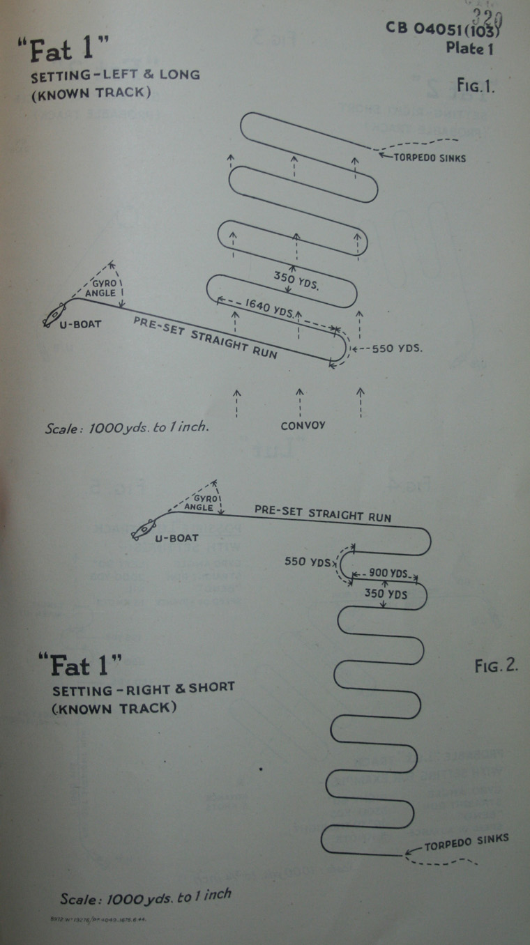
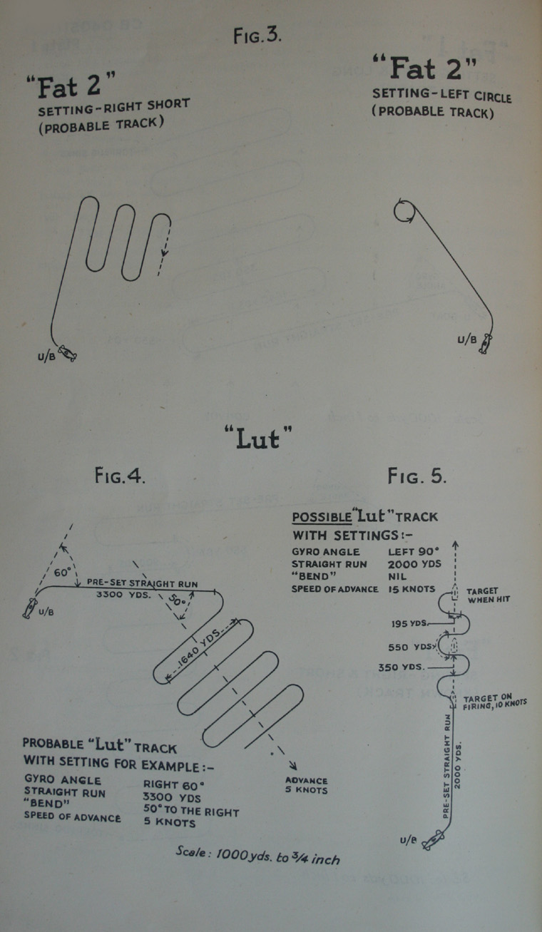
53 |
||||||||||||||||||||||||||||||||||||||||||||||||||||||||
| 110. It will be seen that a torpedo with "Lut" will be valuable for browning a convoy from any direction, and will also be useful against independent ships. Fired against single ships from right ahead or astern, and with curly advance set just in excess of target's speed, the chance of a hit should be great, unless the target zig-zags during the torpedo's approach. | ||||||||||||||||||||||||||||||||||||||||||||||||||||||||
| (x) Pistols. | ||||||||||||||||||||||||||||||||||||||||||||||||||||||||
| 120. The pistols used in U-boat's torpedoes are of several kinds, viz: | ||||||||||||||||||||||||||||||||||||||||||||||||||||||||
| 121. An impact pistol, "G.7.H", "Pi 1". This is described in C.B.(R) 3116, Section 15 (also in C.A.F.O.659/43), with advice for disarming it. It can be used in 21-inch air or electric torpedoes; and by surface ships or U-boats, but is now little used by U-boats. It is fired by a blow end on, or on any of its four lever whiskers. It should be safe whilst in the tube, and should not fire hydrostatically; but its lever whiskers are likely to detonate the torpedo when it strikes the sea bottom. | ||||||||||||||||||||||||||||||||||||||||||||||||||||||||
| 122. A pistol "Pi 2", introduced in 1942, which is impact, and magnetic at option. Externally it is believed to resemble "Pi 1", with the same impact whiskers. Its magnetic portion is of German design, and probably embodied with the pistol itself in the nose pocket. It is used probably only in the electric torpedo "T.3" (paragraph 53), as it requires a supply from the electric battery. Its sensitivity is sufficient to fire 19 feet below the keel of a heavy ship. It is likely to be less liable to premature than was the spinning armature magnetic pistol in use before 1941. | ||||||||||||||||||||||||||||||||||||||||||||||||||||||||
| 123. Another pistol "Pi 3" also impact and magnetic, and again the external parts are believed to resemble "Pi 1". It is probable that "Pi 3" is used only in air torpedoes, where no electric supply is available, and that it acts in conjunction with magnetic detonator gear of the Italian "S.I.C." kind (paragraph 320) situated at the after end of the warhead. If so, degausing will have no appreciable affect against it. | ||||||||||||||||||||||||||||||||||||||||||||||||||||||||
| 124. Yet another type of pistol "Pi-4" is used in the "Gnat" torpedo (paragraph 25). This is thought to be a top insertion pistol, probably of the inertia impact type, allied with magnetic detector gear possibly of the "S.I.C." type. It is likely that several models of this pistol exist. | ||||||||||||||||||||||||||||||||||||||||||||||||||||||||
| (xi) General Information on U-boat Torpedoes. | ||||||||||||||||||||||||||||||||||||||||||||||||||||||||
| 130. The outfit of a typical 500-ton U-boat about December 1943 was 4 "Gnats", and 8 other electric torpedoes most of which could be "Curlies". A few air torpedoes might be substituted, especially on distant stations. | ||||||||||||||||||||||||||||||||||||||||||||||||||||||||
| 131. This armament would enable her to fire a salvo of three electric "Curlies" at ships in convoy, or to fire a "Gnat" at any ship especially an escort ship. With air "Curlies" she might brown a convoy from ranges up to about 10,000 yards. | ||||||||||||||||||||||||||||||||||||||||||||||||||||||||
| 132. The following trends of U-boat torpedo development are apparent: | ||||||||||||||||||||||||||||||||||||||||||||||||||||||||
| Greater use of "Gnat" torpedoes. | ||||||||||||||||||||||||||||||||||||||||||||||||||||||||
| Greater use of magnetic pistols, not only in "Gnat" and "Curly", but also in straight torpedoes. | ||||||||||||||||||||||||||||||||||||||||||||||||||||||||
| Longer range in electric torpedoes. | ||||||||||||||||||||||||||||||||||||||||||||||||||||||||
| Discharge of torpedoes from greater depths. The present limit of about 100 feet is imposed by the torpedo tubes, but both "Gnat" and "Curly" torpedoes would be effective weapons from deeper depths if discharge gear permitted. | ||||||||||||||||||||||||||||||||||||||||||||||||||||||||
| (xii) Torpedo Tubes. | ||||||||||||||||||||||||||||||||||||||||||||||||||||||||
| Some U-boats have been fitted with steel torpedo tubes specially treated to overcome rust. It is thought that this is only due to the copper shortage in Germany - and not for the purpose of firing deep. | ||||||||||||||||||||||||||||||||||||||||||||||||||||||||
| (B) Mines (B2) | ||||||||||||||||||||||||||||||||||||||||||||||||||||||||
| (i) Torpedo mines. | ||||||||||||||||||||||||||||||||||||||||||||||||||||||||
| There are 3 known types of mine laid by U-boats through their torpedo tubes. These are carried in lieu of torpedoes: | ||||||||||||||||||||||||||||||||||||||||||||||||||||||||
|
||||||||||||||||||||||||||||||||||||||||||||||||||||||||
| (ii) Type "GO" mines (E.M.F.). | ||||||||||||||||||||||||||||||||||||||||||||||||||||||||
| Has been laid by minelaying U-boat types VII D, IX D and X B in up to 290 fathoms. | ||||||||||||||||||||||||||||||||||||||||||||||||||||||||
| Charge: Approximately 750 lbs. | ||||||||||||||||||||||||||||||||||||||||||||||||||||||||
| Diameter: 46 ins. | ||||||||||||||||||||||||||||||||||||||||||||||||||||||||
| Moored/Magnetic (recovered). | ||||||||||||||||||||||||||||||||||||||||||||||||||||||||
| May have delay clock. | ||||||||||||||||||||||||||||||||||||||||||||||||||||||||
| 35787 E | ||||||||||||||||||||||||||||||||||||||||||||||||||||||||
54 |
||
CHAPTER XV |
||
TRAINING FOR THE U-BOAT SERVICE IN THE GERMAN NAVY |
||
| (i) General Remarks. | ||
| Enlistment in the German Navy can be voluntary until the age of 17. After that a man called up may not even decide which of the three services he would like to join: he is just drafted where required. For this reason, most young Germans are volunteers in a sense, some by now being well aware of the toll on the Russian front. | ||
| Owing to the lack of conscription between 1918 and 1935, there is undoubtedly a shortage of trained personnel in the technical branches. It is possible, for instance, to become a Petty Officer after one year's sea training, provided the technical background warrants such rapid promotion. Older long-service men who have expected a quiet shore job, have found themselves to their surprise, at sea. | ||
| Germany could obviously not hope, in the time available to her, to build large units and had to resort to big numbers of smaller craft taking less time to build and requiring smaller complements. The main units, until recently, were over-manned in order to give experience to as many officers and ratings as possible. | ||
| Intensive propaganda, advertising high pay, long leave and undoubtedly excellent victualalling has done its utmost to attract young men into the U-boat arm. Once the "U" has prefixed his serial number, he will always be employed in some U-boat establishment if not at sea. | ||
| Although length of training has been cut and recruits lack experience, U-boat losses have increased, and Allied air raids and the Russian front have caused a certain despondency, it cannot be said that the drop in morale is sufficient to presume a marked decrease in fighting efficiency. High hope is placed in new technical developments and a possible come-back in the U-boat arm. | ||
| (ii) Training for Commissioned Rank. | ||
| In the German Navy, the periods into which training for commissioned rank are divided may be roughly expressed as follows: | ||
| (a) New Entry Training. | ||
| (b) Initial Sea Time. | ||
| (c) General Naval Training Course. | ||
| (d) Second Sea Time. | ||
| (a) New Entry Training. An officer recruit selected for the executive branch usually joins at the age of 18 at Stralsund. Here, as ordinary seaman, he undergoes a six months' course in seamanship. During this training the candidate is watched, great importance being placed on his "officer-like qualities". Only the commission of serious offences would cause rejection. | ||
| During this training the trainee holds the rank of "Seekadett" (Cadet Rating). It is estimated that about 1,000 such cadet ratings undergo training at one time, thus producing some 2,000 potential officers annually. | ||
| (b) Initial Sea Time. Cadet ratings having completed their course at Stralsund are sent to sea for a year, usually in smaller types of craft, to gain sea experience. After six months they are promoted Fähnrich (Junior Midshipman). During this initial sea time they never serve in U-boats, irrespective of whether or not they have applied to join this branch of the service. | ||
| (c) General Naval Training Course. When a Junior Midshipman has completed his initial sea time, he is sent on a comprehensive training course at Flensburg-Mürwik. During the latter part of this course, he may specialise in subjects likely to be of use to him in the class of ship in which he is to serve. | ||
| (d) Second Sea Time. As soon as the period of training at Flensburg-Mürwik is completed, the Midshipman goes to sea again. He has, however, only a limited choice of ships, though it is probable that he may join a U-boat. This stage of training lasts for nine months, in the taller three of which the trainee is normally promoted to "Oberfähnrich" (Senior Midshipman). When the second sea service has been completed, the trainee receives his commission as Leutnant-zur-See (Junior-Sub-Lieutenant). | ||
| (iii) Provision of U-boat Officers. | ||
| (a) General. As soon as a Midshipman becomes a Sub-Lieutenant he is likely, if he has spent his second sea time in U-boats, to be appointed as a watch-keeping officer in the same branch of the service. In cases where an officer transfers from surface ships to U-boats it is usual for him to spend six months at a U-boat school, or he may be appointed Second Officer of the Watch to gain sea experience. | ||
| (b) Training of U-boat Commanding Officers. An officer who has completed at least one year as First Lieutenant in a U-boat becomes eligible for training as a U-boat Commanding Officer. The youngest Commanding Officer yet captured, however, was 24 years old. It seems probable that the authorities are selecting officers to train as U-boat commanders who have served previously in other types of vessel, and then completed a year as First Lieutenant in a U-boat; or are recruiting officers directly from surface units as U-boat Commanding Officers. Many naval officers who were seconded to the Air Force during the large-scale attacks of 1940 have been returned to the Navy. These officers appear to receive a large degree of preference in the distribution of U-boat commands. | ||
55 |
|||||||||||||||||||||||||||||||||||||||||||||||||||||||||||||||||||||||||||||
| (c) U-boat Schools. Prospective U-boat Commanding Officers who have no previous U-boat experience are sent to one of the U-boat schools at Pillau and Gdynia for a period of eight weeks, which includes four weeks' school-boat training and four weeks' theoretical instruction. This course can also be taken by Oberfähnrich (Senior Midshipmen), Reserve Officers, Engineer Officers and Senior Chief Petty Officers. | |||||||||||||||||||||||||||||||||||||||||||||||||||||||||||||||||||||||||||||
| If a perspective U-boat Commander has already done this course, he need not repeat it. Irrespective, however, of whether or not he has undergone such a course, he is next sent to the U-boat Commanding Officers' School (Kommandantenschule") at Gdynia for two to three months. | |||||||||||||||||||||||||||||||||||||||||||||||||||||||||||||||||||||||||||||
| (d) U-boat Torpedo Firing Course. Prospective U-boat Commanding Officers, other than those who have not already done this course as First Lieutenants, are sent before taking over commands to the Torpedo Control School at Flensburg, known as the "Unterwasser Torpedo Leitanlage" course. This course usually has been taken by First Lieutenants with the object of ensuring that there are two officers on board who are conversant with under-water torpedo firing. In practice, however, First Lieutenants fire while on the surface. Under-water firing being carried out by the Commanding Officer. This course usually lasts for about three months. | |||||||||||||||||||||||||||||||||||||||||||||||||||||||||||||||||||||||||||||
| (e) Convoy attack teacher for Commanding Officers (F-Gerät). A trainer for officers undergoing courses for U-boat command, known as "F-Gerät" (Fahrt Gerät - Patrol Gear) is situated at Neustadt in a structure near the U.A.A. (U-boat Training School) Post Office building. It consists of a complete U-boat conning tower suspended above a sheet of water with the periscope looking down upon it. On the sheet of water are miniature ships on metal rods. They form convoys which move about at varying speeds and courses, directed by a civilian named Barkow. A variety of weather conditions and visibility can be simulated. The conning tower can be turned and speeds up to 18 knots simulated by moving the ships towards or away from the periscope. Every prospective U-boat C.O. must make fifteen successful attacks on the convoy. Nearly every commanding officer has taken this course and refers to it by saying he has patrolled with Barkow. | |||||||||||||||||||||||||||||||||||||||||||||||||||||||||||||||||||||||||||||
| (f) U-boat Torpedo Firing Flotilla at Gdynia. Having completed their final torpedo firing course, prospective commanders undergo further training with the Torpedo-firing 22nd Flotilla at Gdynia for a period of eight weeks. The only other officers who attend this course are U-boat engineer officers. Having completed his practical experience, a prospective U-boat Captain is ready to stand by his first command. | |||||||||||||||||||||||||||||||||||||||||||||||||||||||||||||||||||||||||||||
| (g) U-boat Commanders' Training Cruise. After he has completed his training, the prospective Commander could volunteer for what was known as his "Konfirmandenfahrt", or training cruise as a supernumerary. This is rarely allowed now - Commanding Officers being considered too valuable to risk in this way. | |||||||||||||||||||||||||||||||||||||||||||||||||||||||||||||||||||||||||||||
| (iv) Training of New Entries ("Rekrutenausbildung"). | |||||||||||||||||||||||||||||||||||||||||||||||||||||||||||||||||||||||||||||
| (a) General. The training of recruits for the German Navy takes place at some 20 different establishments in various parts of Germany and the occupied territories. On enlistment, new entries undergo preliminary disciplinary training ("Rekrutenausbildung") varying in length between eight weeks in the case of technical personnel and eight to twelve weeks in the case of seamen. Such trainees are drafted to training establishments, which are generally under the command of a Captain. Here they are formed into companies ("Kompanien"), each averaging 200 men and commanded either by active or reserve Commanders, Lieutenant-Commanders and Lieutenants. These companies are again sub-divided into platoons ("Züge") of approximately 50 men each, sometimes commanded by junior officers awaiting draft, or by Chief Petty Officers. | |||||||||||||||||||||||||||||||||||||||||||||||||||||||||||||||||||||||||||||
| As soon as a rating arrives at his training establishment, his qualification and standard of intelligence are noted and he is detailed for one of the 17 branches ("Laufbahnen") of the German Navy. Particular note is taken of possible future telegraphists and torpedo ratings, and, to a minor extent, of other technical personnel. To other branches, men are allocated as required. | |||||||||||||||||||||||||||||||||||||||||||||||||||||||||||||||||||||||||||||
| Some youths who have been in the Naval Branch of the "Hitler Jugend", or had some pre-naval training at school, do a reduced preliminary training, and may even be entirely exempted from it. | |||||||||||||||||||||||||||||||||||||||||||||||||||||||||||||||||||||||||||||
| (b) Manning Depots. Preliminary naval disciplinary training is known to take place at the following manning depots: | |||||||||||||||||||||||||||||||||||||||||||||||||||||||||||||||||||||||||||||
|
|||||||||||||||||||||||||||||||||||||||||||||||||||||||||||||||||||||||||||||
| 35787 F | |||||||||||||||||||||||||||||||||||||||||||||||||||||||||||||||||||||||||||||
56 |
||||||||||||||||||||||||||||||||||||||||||||
|
||||||||||||||||||||||||||||||||||||||||||||
| (c) Drafting Depots. Ratings who have completed their preliminary disciplinary training and all seamen awaiting draft are sent to a "Durchgangskompanie" (Drafting Depot), where they receive refresher courses. It is estimated that about15,000 men are distributed in the following drafting depots: | ||||||||||||||||||||||||||||||||||||||||||||
| Bergen (norway), Copenhagen, Cuxhaven, Danzig, Den Haag, Fisherhade, Flensburg-Mürwik, Gröningen, Kiel, Leba, Memel, Neustadt, Norderney, Paris, Plön, Rendsburg, Wangerooge, Wilhelmshaven, Kühlungsborn. | ||||||||||||||||||||||||||||||||||||||||||||
| (N.I.D. Note. Manning Depots are often used as drafting depots.) | ||||||||||||||||||||||||||||||||||||||||||||
| (v) Specialised Training. | ||||||||||||||||||||||||||||||||||||||||||||
| (a) Telegraphists. A telegraphist is sent on a three months' course at Aurich, Gdynia, Kiel, Flensburg-Mürwik, Stralsund or Wesermünde. Training is not only in W/T but also in hydrophone listening and instruction in the use of search-gear. Less successful trainees are sent to special schools at Wilhelmshaven, Borkum or Trondheim, before being sent to sea. | ||||||||||||||||||||||||||||||||||||||||||||
| (b) Signalmen. There are a small proportion of signalmen in the German Navy. They are trained at Flensburg, Cuxhaven or Waren (Lake Müritz) for a period of eight weeks (B3). | ||||||||||||||||||||||||||||||||||||||||||||
| (c) Stokers. Men training as stokers proceed after their preliminary training to Kiel, Stettin, Warnemünde or Wesermünde for engine-room instruction. The establishments at Kiel and Wesermünde are the largest of this kind. A rating undergoes various courses such as "Electrical No. 3" (E3), or "Motor No. 3" (Mo.3), according to whether he is to become an electrical or Diesel stoker. The duration of courses is about eight weeks. | ||||||||||||||||||||||||||||||||||||||||||||
| (d) Torpedo ratings. Men who have been selected for training as torpedo ratings are usually sent on a course at either Kiel, Bremen, Travemünde, Memel, Eckernförde, Pillau, Gdynia, or Warnemünde. The average duration of these courses is eight weeks. | ||||||||||||||||||||||||||||||||||||||||||||
| (e) U-boat Personnel. The specialised training of U-boat personnel is carried out at one of the three U-boat schools at Pillau, Gdynia or Neustadt. At Pillau the school is conducted in the training ship "Robery Ley" and in a shore establishment; the ship produces about 2,000 trained men annually and the shore establishment about 1,000 in the same period. The training ships "Willhelm Gustoff", "Oceana" and "Hansa" are employed as the U-boat school in Gdynia and train about 2,000 men annually. The U-boat school at Neustadt was re-opened during summer 1943. | ||||||||||||||||||||||||||||||||||||||||||||
| (vi) Training of Petty Officers. | ||||||||||||||||||||||||||||||||||||||||||||
| (a) Seaman Petty Officers. Prospective Petty Officers first do a course of field training at Glückstadt or Kiel. Following this, a Petty Officer must undergo some technical course of about eight weeks' duration and generally consisting of gunnery training or torpedo instruction. The present total training period for potential Petty Officers is, therefore, only four months. It is possible nowadays for a rating with special qualifications to be recommended for promotion to Petty Officer after one year's sea service. | ||||||||||||||||||||||||||||||||||||||||||||
| (b) Petty Officer Telegraphists. Petty Officer telegraphists usually undergo their eight weeks' preliminary field training at either Kiel or Flensburg. This is followed by an eight weeks' purely theoretical W/T course at Flensburg. Further practical training of no specific duration takes place either at Flensburg or in one of the depot ships. | ||||||||||||||||||||||||||||||||||||||||||||
| (c) Stoker Petty Officers. Stoker petty officer candidates are usually sent for their preliminary field training at Wesermünde. Afterwards they either stay there or proceed to Kiel, Stettin or Warnemünde to take amongst other "Electrical Course No. 2" (E.2) of "Motor Course No. 2" (Mo.2), depending on the type of machinery in which they are specialsing. | ||||||||||||||||||||||||||||||||||||||||||||
| (d) Torpedo Gunners' Mates. After undergoing his further field training course of eight weeks, a prospective torpedo gunners' mate usually goes to one of the torpedo schools for a short refresher course. It is not thought that any further training is considered necessary in this branch. | ||||||||||||||||||||||||||||||||||||||||||||
| (e) Schools for petty officers are a Buxtehude, Glücksburg, Glückstadt, Kiel, Stettin and Stralsünd. | ||||||||||||||||||||||||||||||||||||||||||||
| (vii) Training of Chief Petty Officers. | ||||||||||||||||||||||||||||||||||||||||||||
| (a) Torpedo and Telegraphist Chief Petty Officers. Torpedo and telegraphist petty officers are promoted to chief petty officers by seniority, or for distinguishing themselves in action. Before the war, it was necessary to serve for 12 years before becoming eligible for promotion. Petty officers when promoted do not receive further training unless they transfer to another branch or receive a commission. | ||||||||||||||||||||||||||||||||||||||||||||
| (b) Chief Stoker Petty Officers. Stoker petty officers from the U-boat arm training to become chief stoker petty officers usually undergo at Kiel or Wesermünde an advanced motor or electrical | ||||||||||||||||||||||||||||||||||||||||||||
57 |
||
| course, known as "Motor Course No. 1" (Mo. 1) and "Electrical Course No. 1" (E.1) respectively. This course lasts six months. It seems to have achieved a large measure of popularity, it is of a high standard and carries extra pay with it. Men who have qualified stand a good chance of being commissioned, as there is a great shortage of engineer officers. | ||
| (viii) Special Courses. | ||
| (a) Gunnery. The Gunlayers' Course No. 3 ("Geschützführer 3" - G.F.3) lasts for eight weeks and includes instruction in 8.8 cm.and 10.5 cm. guns. It is mainly for U-boat ratings and petty officers. | ||
| The Gunlayers' Course No. 2 ("Geschützführer 2 " - G.F.2) lasts for eight weeks and includes instruction in 10.5 cm. guns and larger calibres. It is intended for ratings and for petty officers serving in surface units. | ||
| The Gunlayers' Course No. 1 ("Geschützführer 1 " - G.F.1) lasts for eight weeks and includes instruction in all anti-aircraft weapons of a calibre below 10.5 cm. It also includes instruction in single, double and quadruple mountings. | ||
| (b) Gunnery Schools (Fla.K.S.). Aalborg (Denmark), Ahlbeck (nr. Swinemünde), Dänisch-Nienhoff, Gdynia, Hamburg, Kiel, Le Harve, Misdroy, Narvik, Neuendorf, Niedroy, Ondres, Pillau, Rügenwalde, Swinemünde, Usedom, Wangerooge, Wesel (Reinland), Sassnitz, Mimizan (subsidiary centre - all ranks including petty officer telegraphists). | ||
| (c) Divers Course. The diving course is usually taken by Shipwrights at Kiel. It includes instruction in deep-sea diving and under-water welding, lasting about a year. | ||
| (d) Mining Courses. Ratings known as "Sperrmänner" receive an eight weeks' course at Cuxhaven in one special subject, and do not receive general instruction in mining matters. | ||
| "Sperrmechaniker" (mine artificers) are trained for six months at Cuxhaven. On promotion to the rank of chief petty officer, in this branch, no further training is undergone. If a "Sperr-mechaniker" has completed his course just prior to promotion to petty officer, he will probably be merely required to take a short refresher course. | ||
| "Sperrmeister", or chief petty officers in the mining branch do one year's course at Cuxhaven or Kiel, after which they are never sent to sea again, but are usually placed in charge of shore depots. | ||
| Most officers in this branch are promoted from the lower deck. | ||
| (e) Torpedo Recovery. Ratings and petty officers are often sent on an eight weeks' course in torpedo recovery at Flensburg. | ||
| (f) Torpedo Control. There is a special course at Flensburg, attended mostly by U-boat seamen petty officers, which lasts for eight weeks and deals with under-water torpedo-firing mechanism. | ||
| (g) Radar and G.S.R. Operators. 2-4 months' course at Le Coq (Belgium) and Le Touquet. | ||
| (h) Hydrophone Listening. Hydrophone listening courses for prospective telegraphists are taken at Flensburg and last for eight weeks. These courses are taken in conjunction with qualifying courses in W/T and Search Gear. | ||
| (i) Electric Welders. Stokers do a short course Kiel, usually one welder carried in U-boats. | ||
| (j) Navigation (for ratings). 3 months' course for leading seamen and acting petty officers. | ||
| (k) Ship's Cooks. Do a short cookery course at Gdynia, duration 4 weeks. | ||
| (l) Sick Bay Attendants. Sick bay attendants are trained at either Kiel or Wilhelmshaven for one year before being sent to a naval hospital or drafted to sea. | ||
58 |
||||||||||||||||||||||||||||||||||||||||||||||||||||||||||||||||||||||||||||||||||||||||||||||||||||||||||||||||||||||||||||||||||||||||||||||||||||||||||||||||||||||||||||||||||||||||||||||||||
CHAPTER XVI |
||||||||||||||||||||||||||||||||||||||||||||||||||||||||||||||||||||||||||||||||||||||||||||||||||||||||||||||||||||||||||||||||||||||||||||||||||||||||||||||||||||||||||||||||||||||||||||||||||
U-BOAT BUILDING YARDS |
||||||||||||||||||||||||||||||||||||||||||||||||||||||||||||||||||||||||||||||||||||||||||||||||||||||||||||||||||||||||||||||||||||||||||||||||||||||||||||||||||||||||||||||||||||||||||||||||||
SUMMARY OF U-BOAT BUILDING YARDS. |
||||||||||||||||||||||||||||||||||||||||||||||||||||||||||||||||||||||||||||||||||||||||||||||||||||||||||||||||||||||||||||||||||||||||||||||||||||||||||||||||||||||||||||||||||||||||||||||||||
|
||||||||||||||||||||||||||||||||||||||||||||||||||||||||||||||||||||||||||||||||||||||||||||||||||||||||||||||||||||||||||||||||||||||||||||||||||||||||||||||||||||||||||||||||||||||||||||||||||
| Note. Shipbuilding Yards known to have been, or are, building U-boats are given in order of importance. The measurements of the slipways from air photographs are given as follows: | ||||||||||||||||||||||||||||||||||||||||||||||||||||||||||||||||||||||||||||||||||||||||||||||||||||||||||||||||||||||||||||||||||||||||||||||||||||||||||||||||||||||||||||||||||||||||||||||||||
| (a) The length from the water's edge of caisson to the apparent top of the ways or extreme upper limit. | ||||||||||||||||||||||||||||||||||||||||||||||||||||||||||||||||||||||||||||||||||||||||||||||||||||||||||||||||||||||||||||||||||||||||||||||||||||||||||||||||||||||||||||||||||||||||||||||||||
| (b) The width of the area bounded crane-rails, buildings or unprepared ground. | ||||||||||||||||||||||||||||||||||||||||||||||||||||||||||||||||||||||||||||||||||||||||||||||||||||||||||||||||||||||||||||||||||||||||||||||||||||||||||||||||||||||||||||||||||||||||||||||||||
| Further details of yards, floating and dry docks are contained in C.B. 1818 (slips which have been used for building U-boats are shown in bold type.) | ||||||||||||||||||||||||||||||||||||||||||||||||||||||||||||||||||||||||||||||||||||||||||||||||||||||||||||||||||||||||||||||||||||||||||||||||||||||||||||||||||||||||||||||||||||||||||||||||||
| (i) HAMBURG: | ||||||||||||||||||||||||||||||||||||||||||||||||||||||||||||||||||||||||||||||||||||||||||||||||||||||||||||||||||||||||||||||||||||||||||||||||||||||||||||||||||||||||||||||||||||||||||||||||||
| (a) Blohm and Voss. Building are bounded to North by the Elbe, to South by Kuhwäder Hafen and to East by the Fohr Kanal. | ||||||||||||||||||||||||||||||||||||||||||||||||||||||||||||||||||||||||||||||||||||||||||||||||||||||||||||||||||||||||||||||||||||||||||||||||||||||||||||||||||||||||||||||||||||||||||||||||||
| (i) There are 3 slips on the Northern River side: | ||||||||||||||||||||||||||||||||||||||||||||||||||||||||||||||||||||||||||||||||||||||||||||||||||||||||||||||||||||||||||||||||||||||||||||||||||||||||||||||||||||||||||||||||||||||||||||||||||
| Slips No. 1, 2 and 3 470 x 65 ft. | ||||||||||||||||||||||||||||||||||||||||||||||||||||||||||||||||||||||||||||||||||||||||||||||||||||||||||||||||||||||||||||||||||||||||||||||||||||||||||||||||||||||||||||||||||||||||||||||||||
| (ii) There are 5 slips on the West side of the Werfthafen: | ||||||||||||||||||||||||||||||||||||||||||||||||||||||||||||||||||||||||||||||||||||||||||||||||||||||||||||||||||||||||||||||||||||||||||||||||||||||||||||||||||||||||||||||||||||||||||||||||||
| Slip No. 4 600 x 75 ft. | ||||||||||||||||||||||||||||||||||||||||||||||||||||||||||||||||||||||||||||||||||||||||||||||||||||||||||||||||||||||||||||||||||||||||||||||||||||||||||||||||||||||||||||||||||||||||||||||||||
| " No. 5 690 x 90 " | ||||||||||||||||||||||||||||||||||||||||||||||||||||||||||||||||||||||||||||||||||||||||||||||||||||||||||||||||||||||||||||||||||||||||||||||||||||||||||||||||||||||||||||||||||||||||||||||||||
| " No. 6 770 x 85 " | ||||||||||||||||||||||||||||||||||||||||||||||||||||||||||||||||||||||||||||||||||||||||||||||||||||||||||||||||||||||||||||||||||||||||||||||||||||||||||||||||||||||||||||||||||||||||||||||||||
| " No. 7 900 x 120 " | ||||||||||||||||||||||||||||||||||||||||||||||||||||||||||||||||||||||||||||||||||||||||||||||||||||||||||||||||||||||||||||||||||||||||||||||||||||||||||||||||||||||||||||||||||||||||||||||||||
| " No. 8 250 x 130 " | ||||||||||||||||||||||||||||||||||||||||||||||||||||||||||||||||||||||||||||||||||||||||||||||||||||||||||||||||||||||||||||||||||||||||||||||||||||||||||||||||||||||||||||||||||||||||||||||||||
| (b) Deutsche Werft Finkenwarder. One of the two main depots of Deutsche Werft. THree double longitudinal slips on the south bank of the Norder Elbe. | ||||||||||||||||||||||||||||||||||||||||||||||||||||||||||||||||||||||||||||||||||||||||||||||||||||||||||||||||||||||||||||||||||||||||||||||||||||||||||||||||||||||||||||||||||||||||||||||||||
| Slip No. 1 600 x 100 ft. | ||||||||||||||||||||||||||||||||||||||||||||||||||||||||||||||||||||||||||||||||||||||||||||||||||||||||||||||||||||||||||||||||||||||||||||||||||||||||||||||||||||||||||||||||||||||||||||||||||
| " No. 2 and 3 690 x 165 ft. each. | ||||||||||||||||||||||||||||||||||||||||||||||||||||||||||||||||||||||||||||||||||||||||||||||||||||||||||||||||||||||||||||||||||||||||||||||||||||||||||||||||||||||||||||||||||||||||||||||||||
| (c) Howaldtswerke A.G. Has three slips on the Western side of the Ross Hafen. | ||||||||||||||||||||||||||||||||||||||||||||||||||||||||||||||||||||||||||||||||||||||||||||||||||||||||||||||||||||||||||||||||||||||||||||||||||||||||||||||||||||||||||||||||||||||||||||||||||
| Slip No. 1 640 x 100 ft. | ||||||||||||||||||||||||||||||||||||||||||||||||||||||||||||||||||||||||||||||||||||||||||||||||||||||||||||||||||||||||||||||||||||||||||||||||||||||||||||||||||||||||||||||||||||||||||||||||||
| " No. 2 and 3 640 x 95 ft. each. | ||||||||||||||||||||||||||||||||||||||||||||||||||||||||||||||||||||||||||||||||||||||||||||||||||||||||||||||||||||||||||||||||||||||||||||||||||||||||||||||||||||||||||||||||||||||||||||||||||
59 |
||
| (d) Stulkenwerft. Situated between Blohrn and Voss and the Reihersteig depot of the Deutsche Werft. | ||
| Has one double and two single slips. | ||
| Slip No. 1 280 x 90 ft. | ||
| " No. 2 300 x 40 ft. | ||
| " No. 3 260 x 180 ft. | ||
| (ii) KIEL. | ||
| (a) Germania. 8 slips of between 360 ft. and 710 ft. of which slips 1-4 are covered slips. | ||
| Slip No. 1 360 x 95 ft. | | ||
| " No. 2 410 x 80 " | | ||
| " No. 3 440 x 95 " | covered slips. | ||
| " No. 4 500 x 95 " | | ||
| " No. 5 530 x 55 " | ||
| " No. 6 570 x 110 " | ||
| " No. 7 600 x 80 " | ||
| " No. 8 710 x 115 " | ||
| (b) Deutsche Werke. The southern part of the yard adjoining the Germania yard (see (a)) has been considerably improved. | ||
| There are three slips as follows: | ||
| Slip No. 1 725 x 130 ft. | ||
| " No. 2 600 x 95 " | ||
| " No. 3 1,000 x 200 " | ||
| (c) Howaldtswerke A.G. This yard has been enlarged and modernised. There are 6 slips: | ||
| Slip No. 1 350 | | ||
| " No. 2 450 | x 200 (total width of 3 slips). | ||
| " No. 3 450 | | ||
| " No. 4 480 | | ||
| " No. 5 480 | x 150 ft. (Total width of 2 slips). | ||
| " No. 6 480 x 70 ft. | ||
| (iii) DANZIG. | ||
| (a) Schichau. Main position of Yard front and W. bank of the Tote Weichsel. | ||
| There are 5 slips: | ||
| Slip No. 1 510 x 70 ft. | ||
| " No. 2 550 x 70 " | ||
| " No. 3 590 x 90" | ||
| " No. 4 620 x 95 " | ||
| " No. 5 630 x 120 " | ||
| (b) Danziger Werft. Main establishment on W. bank of Tote Weichsel, to S. of the Schichau Yard. Other positions of the yard are also on S. part of Holen Island. There are 3 slips in use and one under construction will probably have about the same dimensions as Slip No. 1: | ||
| Slip No. 1 510 x 90 ft. | ||
| " No. 2 530 x 80 " | ||
| " No. 3 510 x 70" | ||
| (iv) BREMEN AND VEGESACK. | ||
| (a) Deschimag Bremen. The yard is in two parts, one in the Werfthafen, the other at the head of Hafen A. In addition there are two broadside slips on the S. side of the basin. | ||
| Slip No. 1 435 x 45 ft. | | ||
| " No. 2 450 x 90 " | | ||
| " No. 3 550 x 85 " | Werfthafen. | ||
| " No. 4 610 x 80 " | | ||
| " No. 5 750 x 135 " | | ||
| " No. 6 non-existent | ||
| " No. 7 350 x 50 ft. | | ||
| " No. 8 350 x 70 " | Hafen "A" | ||
| " No. 9 350 x 70 " | | ||
| " No. 10 and 11 600 x 85 ft. each on S. side of Basin. | ||
| (b) Bremer Vulkan (Vegesack). Total of seven longitudinal slips: | ||
| Slip No. 1 400 | | ||
| " No. 2 600 | | ||
| " No. 3 600 | x 400 ft. (Total width of 4 slips). | ||
| " No. 4 752 | | ||
| " No. 5 600 | | ||
| " No. 6 550 | x 270 ft. (Total width of 3 slips). | ||
| " No. 7 580 | | ||
60 |
||
| (v) LÜBECK. | ||
| Flenderwerke. This yard has 5 longitudinal slips and 1 broadside slip: | ||
| Slip No. 1 475 x 75 ft. | ||
| " No. 2 560 x 85 " | ||
| " No. 3 530 x 80 " | ||
| " No. 4 460 x 80 " | ||
| " No. 5 460 x 80 " | ||
| " No. 6 155 x 1,150 ft. (Broadside slip) | ||
| (vi) WILHELMSHAVEN. | ||
| Marinewerft. Two slips which were adapted for U-boat building: | ||
| Slip No. 1 580 x 100 ft. | ||
| " No. 2 580 x 120 " | ||
| (vii) FLENSBURG. | ||
| Flensburger Schiffbau. There are 4 slips in the New Yard which are used for building. | ||
| The old yard is purely for fitting out: | ||
| Slip No. 1 400 x 85 ft. | | ||
| " No. 2 400 x 80 " | | ||
| " No. 3 425 x 120 " | all New Yards | ||
| " No. 2 450 x 85 " | | ||
| (viii) EMDEN. | ||
| Nordsee Werke. Situated at the junction of the Reimerhaven and Industrie Hafen. | ||
| There are 3 longitudinal slips: | ||
| Slip No. 1 550 x 140 ft. | ||
| " No. 2 525 x 90 " | ||
| " No. 3 525 x 90 " | ||
| (ix) ROSTOCK. | ||
| Neptun Werke. There are four longitudinal slips. | ||
| Slip No. 1 600 x 135 ft. | ||
| " No. 2 600 x 75 " | ||
| " No. 3 520 x 75 " | ||
| " No. 4 250 x 45 " | ||
| (x) BREMERHAVEN. | ||
Deschimag (Seebeck): |
||
| (a) There are two slips in the S.W. corner of the Industrie Hafen: | ||
| Slip No. 1 600 x 40 ft. | ||
| " No. 2 280 x 50 " | ||
| (b) 2 Dry docks 530 x 85 ft. | ||
| (Note. No. 1 Dock used for building U-boats). | ||
| (c) Nord Deutsche Werft: | ||
| Slip No. 1 460 x 65 ft. | ||
| " No. 2 300 x 55 " | ||
| " No. 3 320 x 85 " (broadside slip) | ||
| " No. 4 patent slip (cradle 88 x 36 ft.) | ||
| " No. 5 220 x 45 ft. (broadside slip) | ||
| (xi) STETTIN. | ||
| (a) Stettiner Oderwerke A.G. This yard has 4 longitudinal slips: | ||
| Slip No. 1 580 x 82 ft. | ||
| " No. 2 550 x 80 " | ||
| " No. 3 440 x 80 " | ||
| " No. 4 450 x 80 " | ||
| (b) Stettiner Vulkanwerke. The area of this yard extends North along the bank of the Oder as far as the lime kilns "Kalkbrennerei". | ||
| There are 4 groups of slipways: | ||
| Slip No. 1 600 x 90 ft. | ||
| " No. 2 680 x 90 " | ||
| " No. 3 580 x 90 " Slips 1-4 comprise South Group | ||
| " No. 4 600 x 80 " | ||
| " No. 5 300 x 75 " | ||
| " No. 6 180 x 60 " Slips 5 and 6 comprise South Centre Group | ||
| " No. 7 95 x 250 " | ||
| " No. 8 90 x 250 " Slips 7 and 8 comprise North Centre Group (broadside slips) | ||
| " No. 9 | ||
| " No. 10 | ||
| " No. 11 Total area of slips 9-11 450 x 120 ft. (North Group "Kalkbrennerei") | ||
61 |
|||||||||||||||||||||||||||||
APPENDIX |
|||||||||||||||||||||||||||||
ELEMENTARY NOTES ON U-BOATS |
|||||||||||||||||||||||||||||
| (i) Construction: | |||||||||||||||||||||||||||||
| (a) Every U-boat consists of a pressure hull built to withstand great strains and stresses, outside which are various fairings, casings and tanks, built to give a stream-line shape to the pressure hull and conning tower, to provide a flat upper deck and also fuel and buoyancy tanks. The pressure hull of a U-boat is the strongest structure ever produced in marine architecture. Built of 7/8" high tensile steel, it is cylindrical in shape, as being the best section to withstand the great pressures likely to be encountered. Joints are welded and riveted. Frames, bulkheads and the sides of the tanks in the lower part of the hull, add greatly to the rigidity. All hatches, bulkhead doors, torpedo tube caps, glands for propeller shafts and periscopes, hydroplanes and rudders and such fittings are also designed to withstand pressure and under-water blast. The conning tower is an oval shaped pressure tight structure of 1-1/4" high tensile steel. It is amidships and has two watertight hatches, the upper one on the bridge, the lower between the conning tower and control room. These hatches are normally the only two opened when a U-boat is on patrol. The inside of the pressure hull is divided into compartments by bulkheads, to which watertight doors secured by clips are fitted. While these add to the strength of the boat, they are not conducive to comfort or to rapid movement between compartments. The accommodation for the crew is cramped, and on long patrols spare torpedoes and provisions add to the discomfort during the first weeks. | |||||||||||||||||||||||||||||
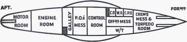 |
|||||||||||||||||||||||||||||
| (b) All U-boats have a flat upper deck extending nearly the whole length of the boat. This deck, usually made of pine planks is about 2' 6" above the crown of the pressure hull supported by light girders. From the deck to the pressure hull is a casing of thin plating perforated by a number of holes to allow free flooding and avoid air pockets when diving. Inside this thin casing are stored wires and ropes, spare torpedo containers, a few high pressure air bottles and non-perishable stores. Similarly, the conning tower is stream-lined by a light casing which forms the bridge, bridge-screen and A/A gun bandstands. From the bottom of the casing to about the centre line of the U-boat, and centrally for about one third of her length, stream-line blisters are built, and the space between them and the pressure hull divided into a number of compartments on each side. These form the external main ballast and fuel tanks. (Note: A 500-tonner, on patrol, does not use her saddle tanks for trimming with the exception of the small quick diving tanks on either side amidships. The only ballast tanks proper used when diving are Nos. 1 and 5 aft and forward, just overlapping the pressure hull and No. 3 port and starboard, inside the pressure hull, and under the conning tower.) The stream-line is completed by fairing's on the bow and stern. In addition this outer hull provides brackets for the rudders, propellers and propeller shafts, torpedo tubes, anchor hawse pipes, etc. | |||||||||||||||||||||||||||||
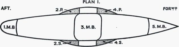 |
|||||||||||||||||||||||||||||
Disposition of Tanks in 500-ton U-boats. |
|||||||||||||||||||||||||||||
|
|||||||||||||||||||||||||||||
| (ii) Fuel tanks: | |||||||||||||||||||||||||||||
| The fuel tanks in a U-boat are self compensating. That is they are always open to the sea at the bottom. The fuel is taken from the top of the tanks, and as it is used, so its place is taken by sea water. Both internal and external ballast tanks are provided. The external tanks like the fuel tanks are permanently open to the sea at the bottom. The internal tanks have large valves in the bottom known as Kingstons. These Kingstons are always open when at sea. At the top of these tanks are vent valves and high pressure blow valves. The vents open to the outside of the boat and let air out when the tanks are being flooded. The "blows" on the other hand admit high pressure air into the top of the tanks to force the water out of the bottom and thus add to the buoyancy of the boat. At sea it is normal for a U-boat partially to fill some ballast tanks to reduce her buoyancy. With the vents shut, the water in the ballast tanks cannot rise higher due to the cushioning effect of the air-lock in the top of the tanks, and in this state the boat is said to be "riding on her vents". To fill the tanks and dive, therefore, it is only necessary to open the main vents. | |||||||||||||||||||||||||||||
| (iii) Periscopes. | |||||||||||||||||||||||||||||
| For observation when submerged, the U-boat has two periscopes. The top 3 feet of each fines away in diameter so that the portion showing above water will only make a small feather. The foremost, or watch periscope, has a top diameter of about 4 inches, surmounted by a 5-inch blob. It is fitted just ahead of the conning tower, but inside the fairing of the bridge structure, with the eye-piece in the control room. This instrument passes through a gland in the pressure hull and the lower part houses, when lowered, into a well let into the control | |||||||||||||||||||||||||||||
62 |
||
| room deck. The lenses give either 1-1/2 or 6 magnifications, and a prism gives a sky search up to the vertical. This periscope is used as little as possible; never if the presence of hostile aircraft was suspected. The attack periscope is used in the later stages of a submerged attack, and the top diameter is only 1-1/2 inches. This glass also has a magnifying power of 1-1/2 or 6, but the top prism only allows for a search of 40 above the horizon, to allow for roll and pitch. In this case, the eyepiece is in the conning tower, and the instrument is usually remote controlled by pedals, the operator sitting on a bicycle saddle. As this periscope is operated from the conning tower, it is some 8-1/2 feet higher than the foremost one. | ||
| (iv) Machinery. | ||
| There are two sets of machinery in the U-boat - Diesel engines for surface propulsion and electric motors for use when dived. The motors also serve as dynamos for charging batteries when on the surface. The maximum speed of a 500-ton type U-boat is 17-1/2 knots at which speed her surface endurance is about 2,700 miles. At a speed of 6-1/2 knots the endurance is about 13,750 miles. The normal cruising speed would probably be in the neighbourhood of 8-1/2 knots with an endurance of about 10,000 miles. When traveling submerged on both motors, the maximum speed is about 8 knots at which speed the battery endurance is only 2 hours. Dead slow speed, about 1 knot, batteries can last for 70 hours. This does not mean, however, that the boat can remain submerged for that time, for the breathing air would become foul long before that, and no captain would normally be prepared to run his batteries right out. Twenty-two hours diving out of every twenty-four can be said to be the maximum in practice. A U-boat can stay submerged up to 36 hours on end before ill health occurs among the crew. | ||
| (v) Seaworthiness. | ||
| In conditions of moderate sea and swell, i.e. when white horses are visible and the wave crests are about 13 feet high, the U-boat proceeding head to sea can maintain an efficient lookout at a speed of about 5 knots. If the sea is rough, and the swell heavy, lookout from the U-boat's bridge is extremely difficult. The bridge is very wet, and uncomfortable, and it is hardly possible to keep a lookout. If proceeding with the sea about 45-90 on either bow, speed can be comfortably be increased. If the swell is abaft the beam "pooping" occurs to a dangerous extent; with the boat rolling heavily large quantities of water are shipped through the conning tower hatch. | ||
| In flat calm, the U-boat bridge is very comfortable. The main ballast tanks can be partially flooded to reduce buoyancy and silhouette, and in these conditions a U-boat should see aircraft before being sighted itself. | ||
| (vi) Effect of Aircraft Machine gun fire. | ||
| The blister tanks are probably vulnerable to .5 machine gun fire, but even very severe damage to blister tanks will not sink a U-boat. The only vital target for cannon or machine gun fire is the guns' crews and bridge watch. There is, however, a case on record in which leaking oil from saddle tanks, penetrated by an aircraft's machine gun fire, was a contributory cause in the subsequent sinking of a U-boat by a surface vessel. | ||
| (vii) Diving. | ||
| As previously stated the U-boat is provided with various main ballast tanks, of which some are inside the pressure hull and others in the saddle tanks. When all main ballast tanks are empty, the U-boat is a normal surface vessel. The U-boat dives by taking in water ballast and using hydroplanes. The design of the tanks is such that when the main ballast tanks are completely full, she will just sink. The desired depth is maintained with the hydroplanes. By pumping water into or out of the internal tanks, or from one tank to another, it is possible to obtain a perfect "trim". The U-boat can then go dead slow on her motors, and only a small movement of the hydroplanes keeps the boat at the depth ordered. When on the surface in an area where air attack is expected, a U-boat proceeds trimmed down, i.e., with certain ballast nearly full to reduce her silhouette. | ||
| To flood the tanks diving vents are opened. Hydroplanes are set to "dive", Diesels are stopped and unclutched, electric motors started and the bridge disappears from sight in about 20 seconds. The U-boat thereafter gains depth at the rate of about 1-1/2 to 2-1/2 feet per second. A U-boat will usually dive to 150 -300 feet before leveling off to ensure being well outside the lethal range of aircraft depth charges. | ||
| A U-boat in rough weather prefers to dive beam-on to the sea, and may alter course for that reason. On the other hand, she will if possible surface head-on to the sea. A U-boat forced to dive as a result of air alarm, may alter course after diving. They can, and sometimes do, dive while on the turn. | ||
| When submerged a U-boat's endurance is limited by: | ||
| (a) Battery capacity, | ||
| (b) High pressure air for blowing tanks, and | ||
| (c) The condition of the air breathed by the crew. | ||
| A submerged U-boat runs on her electric motors, the current for which is provided by batteries which weigh up to 150 tons. This huge dead-weight must be accepted, as the Diesels which draw their air through the conning tower hatch, cannot be used while the boat is submerged. The battery compartments are situated under the living quarters forward and abaft the control room. The state of his batteries provides the U-boat Captain with one of his major anxieties, particularly during the months of long daylight. It takes about 6 hours to charge if the batteries are nearly exhausted, about 2 hours to re-charge if the battery has been conserved all day. Crash dives and evasive tactics require bursts of high speed, which saps the batteries. Therefore the more a U-boat is forced to dive the greater the chance of her surfacing because of exhausted batteries. | ||
| The U-boat carries only enough high pressure air to blow her tanks completely a limited number of times. The high pressure air bottles, which are connected to the high pressure air line, are charged by an air compressor when surfaced. Again, if a U-boat is forced to dive often enough without the chance of re-charging the high pressure air bottles, she will eventually have to surface and remain there. | ||
| Fresh air which the U-boat takes down when she dives would, if not purified, be just fit to breathe at the end of 36 hours. A man absorbs oxygen and exhales CO2 which is a poisonous gas. When working hard or when excited, he uses five times as much oxygen as when asleep, so again, the more he is harried and hunted, the more quickly will he be exhausted. | ||
| C. 3578/ Wt. 19276-Pk. 4049 1575 7/44 D.L. G. 338 | ||