|
|||||
FORMER GERMAN SUBMARINE TYPE XXI |
|||||
SHAFTING AND BEARINGS |
|||||
SUMMARY |
|||||
| A necessary complex shafting coupling arrangement has resulted from the geared drive propulsion setup on the type XXI submarine. On each of the two shafts, in addition to the normally required shaft brakes and main thrust bearing, there are two pneumatic-hydraulic operated jaw clutches for use with the diesel engine and main motor, one cone type friction clutch for use with the silent motor, and a vulcan coupling for use as a vibration dampener. A shaft synchronism indicator and an interlocking device between the main and creeping motor couplings add to the complexities of this setup. | |||||
| A "Huhn carboplan" stern tube seal, similar in principle to the "Syntron Seal" (installed experimentally on the SS 489), is used on this type of vessel. | |||||
May, 1946 |
|||||
PORTSMOUTH NAVAL SHIPYARD, PORTSMOUTH, N. H. |
|||||
|
|||||
SHAFTING AND BEARINGS |
|||||
| 1. INTRODUCTION | |||||
| NavTechMisEu technical report No. 303-45 entitled, "Submarine Main Propulsion Equipment and Arrangement" gives information and plates relative to the shafting arrangements on the type XXI submarines. This present report will not go into any detail on any shafting particulars where already adequately covered in the above-mentioned document. | |||||
| 2. GENERAL DESCRIPTION | |||||
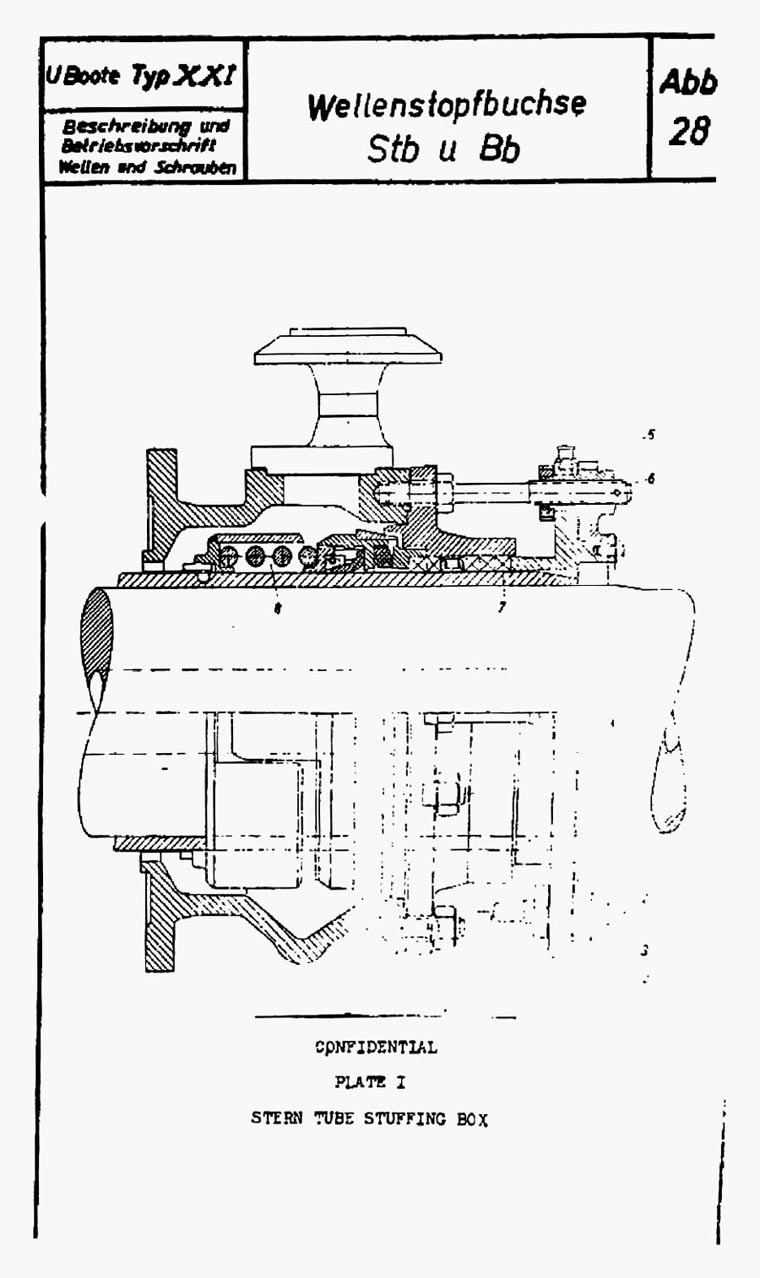
| The shafting layout is shown on plate I under group S40. This plate is self explanatory. The two jaw clutches shown are operated by either power or hand. When in power operation an air on oil cylinder in combination with a hydraulic cylinder and piston is used. The creeping motor friction clutch is operated by hand. The creeping motor friction clutch is operated by hand. The interlocking device between it and the main coupling prevents it from being engaged when the main coupling is engaged. | |||||
| The hydraulic "vulcan" coupling is used only as a shock absorber, preventing the transmission of instantaneous forces from the diesel engine to the reduction gear teeth, as well as reducing power surges to the diesel engine resulting from rough surface operating conditions. No provision is made for rapid dumping of the oil from the coupling, thereby limiting its use. The diesel jaw clutch (located forward of the main motor reduction gear) is used for disengaging the diesel engine from the propulsion shaft under all operating conditions. It has a tendency to stick when thrown with a load on it from either the diesel engine or from the propeller drag. However, information obtained from U.S. operating personnel indicates that this has not given very much trouble to date. | |||||
| The two jaw clutches can only be engaged when the driven and driver shafts are in synchronism - the device for indicating this state is described in the NavTech report mentioned in the introduction. | |||||
| The clutch operation is such as to give the following power combinations on each propeller shaft: | |||||
| a. power on the shaft from the main engine, with the main motor idling. | |||||
- 2 - |
|||||
|
|||||
| b. power on the shaft from the main engine augmented by the main motor. | |||||
| c. power on the shaft from the main motor, with the main engine stopped. | |||||
| d. power on the shaft from the creeping motor, with the main engine and main motor stopped. | |||||
| e. power on the shaft from the creeping motor, with the main engine and main motor operating as a generator unit not connected to the propeller shaft. | |||||
| In addition to the individual thrusts incorporated on the main and pinion gear shafts of both reduction gears, a propeller thrust is installed just aft of the main coupling on the propeller shaft. The main thrust is pressure lubricated and does not have a built-in cooling system for the lubricant as on previous German submarine types. | |||||
| The shafting line runs at an angle of 3°12' to the centerline in the horizontal plane. This comparatively large angle is necessary in order to obtain sufficient room outboard of the main shaft for the main motor and its reduction gear. The shafting line crosses the centerline approximately 11 feet forward of the c.g. (when submerged) resulting in a reverse moment arm of approximately 10". In the vertical plane the shafting line runs at an angle of approximately 0°40' to the base line. The projected line passes about 1 to 1.5 feet below the c.g. (submerged). | |||||
| One strut and one stern tube bearing are installed on each shaft. The distance between centers is approximately 21.7 feet. The bearings are inlaid with either lignum vitae or a type of phenolic material. When the former is used, the lower third of the bearing is with end-grained wood and the upper two thirds is with flat-grained wood. The strut bearing surface is 27.6 ins. long, while the surface of the stern tube is 23.6 ins. long. | |||||
| The stern tube packing gland is of particular interest. The installation is shown on plate I. The inboard part is comprised of 5 rings of cotton or flax packing and a standard lantern ring. This can be taken up uniformly with the gearing arrangement shown. The after part of the gland, (8), is denoted as a "Huhn Carboplan" packing. It functions on a similar principle to that employed by the "Syntron" seal. | |||||
- 3 - |
|||||
|
||||||||||||||||||||||||||||||||||||||||||||||||||||||||||||||||||||||||||||||||||||||||||||||
| All parts of this seal rotate with the shaft. The carbon ring on the inboard end forms a seal with the vertical surface of the metallic ring on the outboard end of the flax stuffing box. The rubber ring shown forms the necessary seal between the "Huhn" packing and the shaft. The syntron seal has two vertical bearing surfaces compared with the one on the German seal - however, when operating under submergence pressures only the inboard seal of the former functions, thereby eliminating the need for the two sealing surfaces. For the installation of either type of seal, a removable shaft flange and a tapered bushing surface are required. | ||||||||||||||||||||||||||||||||||||||||||||||||||||||||||||||||||||||||||||||||||||||||||||||
| The U-2513 on a deep dive to 450 feet had practically no leakage from either shaft gland. On this occasion, the flax packing had been taken up slightly to stop surface leakage prior to descending to this depth and required no further adjustment. The continued operation of both the U-2513 and U-3008 should furnish valuable information on the effectiveness and value of this type of seal for stern tubes. | ||||||||||||||||||||||||||||||||||||||||||||||||||||||||||||||||||||||||||||||||||||||||||||||
| 3. INDIVIDUAL COMPONENTS | ||||||||||||||||||||||||||||||||||||||||||||||||||||||||||||||||||||||||||||||||||||||||||||||
|
||||||||||||||||||||||||||||||||||||||||||||||||||||||||||||||||||||||||||||||||||||||||||||||
- 4 - |
||||||||||||||||||||||||||||||||||||||||||||||||||||||||||||||||||||||||||||||||||||||||||||||
|
||||||||||||||||||||||||||||||||||||||||||
|
||||||||||||||||||||||||||||||||||||||||||
| 4. CONCLUSIONS | ||||||||||||||||||||||||||||||||||||||||||
| The complexity of the shafting layout with its numerous clutches and their associated gear makes the maintenance of the units involved extremely difficult. To effect repairs to even some of the smaller units, extensive dismantling is required. However, it is believed that, once accepting the necessity for the power units and reduction gears in the machinery layout, the shafting arrangement is in accordance with U.S. standards. The vulcan coupling is needed to prevent the transmission of excessive vibrating forces to the reduction gear teeth. Although this coupling could be adapted to rapidly disengage the diesel from the main shafting, this feature was not required with the addition of a desirable quick-operating jaw clutch between the two reduction gears. | ||||||||||||||||||||||||||||||||||||||||||
| The installation of the "Huhn carboplan" seal to limit leakage through the stern tube packing is of particular interest. This seal has been backed up with a standard packing gland to insure safety. The feasibility for this type of packing for stern tubes can be more readily determined after prolonged operation of the two type XXI vessels now in U.S. custody. | ||||||||||||||||||||||||||||||||||||||||||
- 5 - |
||||||||||||||||||||||||||||||||||||||||||