FORMER GERMAN SUBMARINES |
||
INTRODUCTION |
||
Authority |
||
| The design studies, of which this report is a part, have been made under the authority of the Chief of Naval Operations restricted letter Op-23C-1-Serial 217423 of 28 May, 1945. This letter directs the Naval Shipyard, Portsmouth, to prepare design studies, perform tests and to compile reports on each type of submarine. | ||
| Purpose | ||
| This report has been prepared to describe the material components of a single type of vessel. In addition to the purely descriptive matter, the report includes comparison with related U.S. Naval or commercial practices in places where it is believed such comparison is of value in determining the basis of design. | ||
| Where comparisons are made, they are intended to assist in evaluating the particular circumstances, and are not made for the purpose of questioning the existing practice. To the extent that any single item has merit, it has been described, but it is fully recognized that the good points of a single component do not necessarily indicate that an entire system or method is superior. | ||
| Method of Compilation | ||
| This report has been prepared in accordance with the division of subject matters given in the Ship's Material Section of the Navy Filing Manual. All of the "S" groups are represented by text material of by cover pages which either refer to other report sections for related text or indicate the inapplicability of the section. | ||
| In view of the applicability of the Navy Filing Manual as an index for the report no separate index has been prepared. | ||
- 1 - |
||
| Each "S" group in the report on 9C40 vessels is complete within itself and consists of a title page and summary, a description of the appropriate design elements and related remarks and conclusions. The corresponding section in the reports on other types of vessels is not, generally speaking, complete in itself, but describes the changes from the 9C40 vessels which were made when designing the corresponding elements in that one type. This procedure has saved a great amount of duplication, for all the later types were related in varying degrees to the 9C40 and in a number of respects are identical. | ||
| In certain cases, it has been necessary to divide sections into their sub-groups because of the extent or character of the matter described. Generally speaking, however, the subject matter has been briefed by "S" groups without employment of sub-numbering. | ||
| In the case of sound isolation it has been considered preferable to centralize all information in the S-23 group. Sound isolation is applied to components of many different systems and the extent could not be indicated without employing this method. | ||
| Similarly, primary reference to main motors and generators is made in S63, in order to avoid segregating individual aspects of single machines under two "S" groups. | ||
| Reference Material | ||
| At the end of the report is a bibliography which has been cross-listed by the "S" group number. | ||
| The first part of the bibliography is an alphabetical list of the reference material. Each one of the titles is given in German and in English and each title is numbered. The titles are shown in two groups: first, those applicable generally, and second, those applicable to the one type of vessel. | ||
| The second part is a list by "S" groups giving the numbers of the reference titles which were used in the compilation of that section. This is also divided into two groups: first, those applicable to the vessel as a whole, and second, those applicable to parts of the vessel. | ||
| Few of the reports on exploitation of individual components by other agencies, or on operating experience with the vessels, have been received. All reports received as of 22 July, 1946 are listed in the bibliography, but the | ||
- 2 - |
||
| disbanding of the German Submarine Planning group at Portsmouth, as at present constituted, prevents modification of report sections to incorporate material which mat be received at some later date. | ||||||||||||||||||||||||||||||||
| The text and plan material in the bibliography has been used to supplement personal observations by the personnel of the group on board available vessels. | ||||||||||||||||||||||||||||||||
| The vessels on which it was possible to make personal observations are as follows: | ||||||||||||||||||||||||||||||||
|
||||||||||||||||||||||||||||||||
- 3 - |
||||||||||||||||||||||||||||||||
| SHIPS MATERIAL GROUP. | |||||||||||||||||||||||||||||||||||||||||||||||||||||||||||||||||||||||||||||||||||||||||||||||||||||||||||||||||||||||||||||||||||||||||||||||
| As taken From Navy Filing Manual. | |||||||||||||||||||||||||||||||||||||||||||||||||||||||||||||||||||||||||||||||||||||||||||||||||||||||||||||||||||||||||||||||||||||||||||||||
|
|||||||||||||||||||||||||||||||||||||||||||||||||||||||||||||||||||||||||||||||||||||||||||||||||||||||||||||||||||||||||||||||||||||||||||||||
- 1 - |
|||||||||||||||||||||||||||||||||||||||||||||||||||||||||||||||||||||||||||||||||||||||||||||||||||||||||||||||||||||||||||||||||||||||||||||||
| SHIPS MATERIAL GROUP - Continued. | |||||||||||||||||||||||||||||||||||||||||||||||||||||||||||||||||||||||||||||||||||||||||||||||||||||||||||||||||||||||||||||||||||||||||||||||
|
|||||||||||||||||||||||||||||||||||||||||||||||||||||||||||||||||||||||||||||||||||||||||||||||||||||||||||||||||||||||||||||||||||||||||||||||
- 2 - |
|||||||||||||||||||||||||||||||||||||||||||||||||||||||||||||||||||||||||||||||||||||||||||||||||||||||||||||||||||||||||||||||||||||||||||||||
|
|||||||||||
FORMER GERMAN SUBMARINE TYPE XXI |
|||||||||||
DESIGN, MODELS AND PLANS |
|||||||||||
SUMMARY |
|||||||||||
| This type of vessel is a radical departure in hull form and in certain mechanical and electrical respects from earlier types of German submarines, for the purpose of increasing submerged speed, and permissible submergence depth. | |||||||||||
| The changes have been made at the expense of surface speed and other surface characteristics. Further, the design was not completely thought out before the beginning of construction, and has a number of shortcomings as a result, as described in the pertinent sections of this report. | |||||||||||
| Nevertheless, the results obtained indicate the need to exploit the possibilities of the type to the maximum. | |||||||||||
July, 1946 |
|||||||||||
PORTSMOUTH NAVAL SHIPYARD, PORTSMOUTH, N. H. |
|||||||||||
- 1 - |
|||||||||||
|
||||||||||||||||||||||||||||||||||||||||||||||||||||||||||||||||||||||||||||||||||||||||||||||||||
| The principal characteristics of the type 21 submarines as given in NavTechMisEu Report 312-45, are summarized herein. The vessels depart in certain respects from the data given, and where they do, reference has been made to the fact in the proper report section. The designed characteristics, which were not met in all respects, as as follows: | ||||||||||||||||||||||||||||||||||||||||||||||||||||||||||||||||||||||||||||||||||||||||||||||||||
|
||||||||||||||||||||||||||||||||||||||||||||||||||||||||||||||||||||||||||||||||||||||||||||||||||
| On vessels observed, the stabilizer fins did not extend beyond the full beam of the vessel, although as designed, the stabilizers were to have been 26'-3" wide. | ||||||||||||||||||||||||||||||||||||||||||||||||||||||||||||||||||||||||||||||||||||||||||||||||||
- 2 - |
||||||||||||||||||||||||||||||||||||||||||||||||||||||||||||||||||||||||||||||||||||||||||||||||||
|
|||||||||||
| Displacement on both vessels was found to be about 40 tons greater than the design figure above. | |||||||||||
| The cruising radius and the speeds on main engines were modified, in the vessels observed, by the removal of the superchargers, which reduced the engine horsepower and efficiency. | |||||||||||
| Submerged speeds did not, so far as can be determined, reach 18 knots on actual vessels. | |||||||||||
| Torpedo stowage, including the tubes, for 23 torpedoes exists, but it is necessary to retain three idle positions to permit withdrawal of torpedoes from tubes for servicing. The actual total torpedoes carried is, therefore, 20. | |||||||||||
| Additional details will be found in the appropriate sections. | |||||||||||
| Wind tunnel tests on the hull of this type of vessel are described in NavTechMisEu Report 188-45. | |||||||||||
| Plotted wave formation at three speeds is included among the information in the Tests for Type XXI Submarines. | |||||||||||
| Discussion of the specifications will be found in the S1-7 section of the report. | |||||||||||
| There were many changes from design during the course of constructing these vessels. They include, in addition to the removal of the superchargers and reduction in stabilizer area aforementioned, the following: | |||||||||||
| a) Simplification of hydraulic controls | |||||||||||
| b) Modification of muzzle door operating gear | |||||||||||
| c) Alteration of battery ventilation | |||||||||||
| d) Many minor but cumulative alterations to the outer shell and fairwater to reduce drag caused by excessive size of flooding and venting openings, and to arrive at a satisfactory compromise bridge structure | |||||||||||
| e) Elimination of the negative tank | |||||||||||
| f) Installation of 9 meter instead of 7.5 meter high-angle periscopes | |||||||||||
| g) Provision of a forward-aft antenna with one end supported on a faired stanchion aft on the superstructure | |||||||||||
| h) Installation of piping for automatic depth control and hovering gear. | |||||||||||
- 3 - |
|||||||||||
|
|||||
FORMER GERMAN SUBMARINE TYPE XXI |
|||||
DESIGN OF VESSEL |
|||||
SUMMARY |
|||||
| Comments are generally as given in the same section for 9C vessels. The drafts of individual books available show great efforts being made to make the books for this type more concise than those for previous classes, by eliminating from them detailed information previously included. Further, the war conditions affected the accuracy of the books for this class of vessel more than they did those for earlier classes, and the available vessels have been found to depart from the text in more particulars than do vessels of earlier types. The principle on which the informational material is based remains unchanged, nevertheless. | |||||
March, 1946 |
|||||
PORTSMOUTH NAVAL SHIPYARD, PORTSMOUTH, N. H. |
|||||
|
||||||||||||||||||||
FORMER GERMAN SUBMARINE TYPE XXI |
||||||||||||||||||||
|
||||||||||||||||||||
SUMMARY |
||||||||||||||||||||
| Information with respect to administration of the shipbuilding, inspections and planning, preparations for building, moulds, launching and docking is available in the reports of the Naval Technical Mission in Europe which cover these phases of the German Shipbuilding program. Inasmuch as no local information supplements these reports, this page is inserted for reference. | ||||||||||||||||||||
March, 1946 |
||||||||||||||||||||
PORTSMOUTH NAVAL SHIPYARD, PORTSMOUTH, N. H. |
||||||||||||||||||||
|
|||||
FORMER GERMAN SUBMARINE TYPE XXI |
|||||
TRIALS |
|||||
SUMMARY |
|||||
| The trial book (Tests for Type XXI Submarines) is similar in general layout to the one described for the 9C vessels, but as the arrangement is different and the items covered do not all duplicate those on the earlier vessel types, a description is given below. | |||||
| The book is divided under the following principal headings: | |||||
| A. Forward. | |||||
| B. Principal characteristics. | |||||
| C. Tests of individual systems. | |||||
| D. Questions to be answered by the trial board. | |||||
| E. Advice on special reports. | |||||
| F. Trials by other agencies. | |||||
| G. Final report. | |||||
| H. Tabulated material and trial reports. | |||||
| There are 54 pages of text material describing what is covered under headings A to G, inclusive. Points covered in addition to the headings listed in the 9C report are: | |||||
| a) Condition of buoyancy. | |||||
| b) Preliminary and final inclining experiment. | |||||
| c) Sallying ship. | |||||
| d) Limiting rpm. | |||||
| e) Turning circles and turning rates. | |||||
| f) Behavior when stopping vessel. | |||||
| g) Behavior at sea, and influence of wind on maneuvering. | |||||
| h) Snorkel tests. | |||||
| i) Dynamic stability. | |||||
| j) Depth control when firing torpedoes. | |||||
| k) Communications control. | |||||
| l) Static dive. | |||||
| m) Quick dive. | |||||
| n) Deep dive as a substitute for pressure dock test. | |||||
| o) Tests of noises emanating from the ship. | |||||
| p) Much more complete tests of major components and single systems, effecting main engines, main motors, battery, ballast tank flooding, negative tank, rudder, log, hydraulic system, torpedo handling, ship's heating and cooling, air regenerating, refrigeration, WC, washing arrangements and galley equipment. | |||||
| The questions which cover nineteen pages, pertain to weights and stability, surface characteristics, submerged characteristics, compartmentation, each system, diving and | |||||
|
|||||
| depth control, compensating and drain arrangements, ship control, arrangements for arms and armament, arrangements for the crew, rescue arrangements, and to allowance lists. | |||||
| The tabulated material, the curves and charts cover more ground than those for the 9C, and in addition, provide information as to test dives made to determine the effect of certain changes in the hull, with report thereon. The book also contains a set of wave form curves at four rates of speed. | |||||
| Comment: | |||||
| The type 21 test book has been of great value in the preparation of the reports on the various portions of the vessel. The data actually provided is not complete, although the data required by the text is a good deal more thoroughgoing than that required for 9C vessels. | |||||
| The test book is a valuable reference work, and covers in a formal manner the same ground which is covered on full scale trials in U.S. Naval practice. | |||||
- 1 - |
|||||
|
|||||
FORMER GERMAN SUBMARINE TYPE XXII |
|||||
HULL STRUCTURE |
|||||
SUMMARY |
|||||
| The type 21 hull is of great interest in all respects, and while the design has in part been compromised by the attempt to work out the solution partly in terms of preceding practice, the hull is deserving of detailed analysis. | |||||
July, 1946 |
|||||
PORTSMOUTH NAVAL SHIPYARD, PORTSMOUTH, N. H. |
|||||
- 1 - |
|||||
|
|||||
| 1. General | |||||
| The vessel consists of a pressure hull which for part of its length in section like an inverted figure 8 and for the remainder is cylindrical, with truncated conical end section having fabricated stern end bulkhead and cast forward end bulkhead, a conning tower which is oval in horizontal section with a cast top, a system of external ballast and fuel tanks enclosed in a faired envelope, and a fairwater for the conning tower which includes a bridge. The designer's depth is 135 meters (440') with a safety factor of 2.5. | |||||
| 2. Pressure Hull | |||||
| The upper cylinder of the pressure hull has a diameter of 5300 mm (17.38') with maximum plate thickness of 26 mm (1.02") and external bulb tee frames 240 x 11 (9.44" x .43") on 800 mm (31.5") centers. The lower section which is not a true circular section except in the way of the two end compartments, and is further discontinued in the way of the machinery compartments, has 18 mm (.71") plating, a flat plate keel 1000 mm x 40 mm (39.37" x 1.58") at the bottom, and 140 x 7 (5.51" x .28") bulb tee internal frames on 800 mm centers. | |||||
| At the point of intersection of the upper and lower segments of the hull, heavy transverse beams extend across from side to side, and the flanges and webs of the external frames are carried down along the lower segment and are tapered off to the plating. The deck carried on these beams is of 18 mm (.71") material, and the beams themselves are tees made from halves of NP40 (standard 15.76") I-beams on 400 mm (15.76") centers. At the bottom of the tub there is, in addition, a 10 mm (.39") decal supported on 285 x 100 x 15 (11.2" x 3.94" x .59") flanged floors on 400 mm centers. | |||||
| At the ends of the pressure hull were the fairing of the outer envelope introduces minimum clearances between the pressure hull and exterior tank plating, internal frames are substituted for external frames. At the same time, in order to conserve space within the hull, the scantlings of the frames are reduced from 220 x 11 to 160 x 7 (5.51" x .28") to offset which frame spacing is reduced from 800 mm to 400 mm (15.75"). | |||||
- 2 - |
|||||
|
|||||
| Plating thickness is likewise reduced, but on a more gradual basis, throughout the length of the tapered sections at the ends of the vessel. Lightest plating is 12 mm (.47") on a diameter of 1492 mm (4.90'). | |||||
| Transverse framing is employed except in the way of the variable tanks, where there is an elaborate system of floors extending up to the pump room deck, and longitudinal frames. The pump room deck is of 26 mm (1.02") material. | |||||
| Pressure hull plating and framing material, and as well, the material for the end bulkheads and their stiffness, is steel 52M. Material for cold-formed frames is aluminum-normalized steel 52 AM. | |||||
| In addition to the bulkheads at the ends of the pressure hull, five fabricated pressure hull bulkheads are provided, dividing the hull into six pressure compartments. These bulkheads are not intended to withstand full submergence pressure, and are further not designed with the same factor of safety. The test pressure corresponds to 50 m (159.0') submergence and the designed safety factor at that pressure is 1.5. | |||||
| One light water-tight bulkhead is fitted in the machinery compartment, between the engine room and the maneuvering room. | |||||
| Pressure hull openings consist of a patch for auxiliary machinery access in the engine room, one battery patch in the after battery, and two patches in the forward battery compartments, access hatches in the maneuvering room and galley, conning tower lower hatch, two periscope openings and one entering opening, and a torpedo hatch in the forward compartment. Attention is invited to the absence of a patch for the main engines. | |||||
| Compensation for hull openings is of the same character as that on previous types. | |||||
| There are no true pressure tanks within the pressure hull proper, but the WRT tanks and forward trim tanks are in the tub which is below the torpedo room, and the after trim tank is located in the tub below the after compartment. Further, another pressure | |||||
- 3 - |
|||||
|
||||||||||||
| tight structure built below the pressure hull in the way of the engine room houses the bilge water tank and two tanks into which oil from the hydraulic clutches is dumped. | ||||||||||||
| The conning tower is similar to those on earlier vessels in size, in scantlings and in material except that the top casting is identified as special material Wh oMo with carbon .2-.25, silicon .35-.50, manganese 1.0-1.2 and vanadium .1-.15, and possessing physical characteristics as follows: | ||||||||||||
|
||||||||||||
| The entire pressure hull is welded except for the patches mentioned above and door frames in pressure bulkheads. Intermittent welding is used only on the stiffeners of the one light watertight bulkhead. | ||||||||||||
| 3. Outer Shell | ||||||||||||
| The outer shell is generally speaking, an envelope enclosing the entire vessel. There is no true, separate, superstructure as such, for several of the exterior compartments are built as saddle tanks extending across above the top of the pressure hull, and the free flooding space below the superstructure deck is limited to those parts of the structure which enclose duct work, or which are cut away for access purposes. | ||||||||||||
| The outer hull encloses the bow and stern buoyancy tanks, 5 main ballast tanks, seven normal fuel oil tanks, two variables ("regelbunker" and "regelzelle") and a pressure proof void space which was originally a negative tank but which has had the flood valves removed and is known to have been used as an uncompensated fuel tank. It also encloses several ballast compartments, one of which extends all the way to the superstructure deck abreast of the torpedo room, and a large free flooding space aft along the sides of the vessel. | ||||||||||||
- 4 - |
||||||||||||
|
|||||
| The tanks are not distributed horizontally along the hull as had been previous practice, but are superposed one upon another. Further, the location of the end bulkheads of the tanks is modified as made necessary by considerations of physical shape and stability. For example, at frame 22.4, MBT 1 is over NFO 3a which again is over a ballast stowage compartment. At frame 32, there is no free flooding space over NFO 4a, over MBT 2, which in turn is over NFO 3a, inasmuch as this tank extends from the after end of MBT 1 well forward under MBT 2. | |||||
| Tank test pressures are 17.5 psi over the base line for fuel oil tanks, and 4.4 psi over the top of the tank under test for main ballast tanks. | |||||
| Exterior tank plating is 5 to 8 mm (.20" to .31") thick. For variable tank, trim tank and WRT plating, see above under the description of the main pressure hull. | |||||
| Framing is generally bulb tee sections 60 x 5, (2.36" x .20") above and 80 x 5.5 (3.15" x .22") below, on 400 mm (15.75") centers. The two sizes are butted and welded to complete a single frame from the deck to the bottom of the lowest tank. | |||||
| Frames are discontinuous in the way of flood valves and certain of the flooding openings, and where this occurs the frames are terminated on longitudinal headers. | |||||
| Radial bracing of the shell framing is provided by means of 100 x 25 x 5 (3.94" x .98" x .20") Yoder angles. | |||||
| Two stringers, run for about half the length of the vessel amidships, provide additional support for the light plating and framing. Scantlings are 120 x 5 (4.75" x .20"). | |||||
| Tankage bulkheads run from 5 mm (.20") to 8 mm (.31") thick, the usual thickness being 6 mm (.24"), and are stiffened by bulb tee sections of appropriate size, usually on 400 mm centers. | |||||
- 5 - |
|||||
|
|||||
| The material for plates and shapes are the same as those on earlier types of vessel. | |||||
| The bridge and fairwater structure serves as well as a housing for the induction and exhaust air outboard valves, for two twin 20 mm gun turrets and operating gear, and for related ready service and spare barrel tanks. | |||||
| Plating is generally 4 mm (.16") thick, but splinter protection 17 mm (.67") thick is provided for the bridge and the gun positions across the top as well as along the sides and at the ends. The material for the splinter protection is identified as Wsho/Mo, but its characteristics are not otherwise known. | |||||
| 4. Keel | |||||
| The vertical keel extends aft from the fabricated forward structure, forming a deep centerline division extending up through the forward trim tanks and WRT tanks, to the forward end of the forward battery, where it is reduced in depth to 285 mm (11.2") and extends aft at that depth to the after end of the after battery, except for the section in the way of the variable tanks, which is carried as a centerline bulkhead up to the pump room deck. Aft of the after battery it is carried at the full depth from the sole plate to the bottom of the pressure hull as far as the forward end of the after trim tank. It is carried aft through the after trim tank, but does not extend below it, as the longitudinal member at the bottom of the vessel is a bulb tee 120 x 6.5 (4.72" x .26"). Connection is provided at the after end of the trim tank to the cellular structure which carries aft into the tail of the vessel. | |||||
| 5. Stern | |||||
| The stern frame of a casting (a weldment is permitted by the specifications) with carriers for the rudder and for the stern planes. | |||||
| Also at the after end of the vessel is a pair of fins which serve the dual purpose of stabilizers and struts for the propeller shaft bearings. As shown on plans, the fins are the widest part of the vessel, but on U-2513 and U-3008, the ends have been omitted. | |||||
- 6 - |
|||||
|
|||||
| 6. Foundations | |||||
| Foundations are similar in design and material to those on earlier types, except as modified by the introduction of reduction gears on this type of vessel. | |||||
| 7. Comments | |||||
| The hull structure is an interesting solution to the problem presented, and is a radical departure from previous German practice. At the same time, a number of the design details could have been improved. A number of details characteristic of previous types have been retained. | |||||
| The method of connecting the upper and lower segments in the way of the battery compartments has been criticized by the Germans, who have ascribed the failure of the lower segment under test at less than designed collapse pressure to the manner of connecting the external frames to the internal frames and the cross beams. | |||||
| With specific reference to the external frames, attention is invited to the fact that although they are deeper, their dimensions in other respects do not vary materially from those on the 9C vessels. Flanges have not been widened to improve the lateral stability of the frame section. | |||||
| Further criticism can be leveled at the design on the score of unsatisfactory bulkheading, as the collapsing pressure for the pressure tight bulkheads is only half the designer's submergence depth for the hull. | |||||
| Again, the retention of bolted plates, and of rivets in shear, as elements of hull opening design, is questionable. | |||||
| The interruption of the circular section at the bottom of the vessel, and the substitution of a heavy sole piece, an additional deck and floors also appears to be unfortunate from a stress distribution standpoint. | |||||
- 7 - |
|||||
|
|||||
| The tankage design is very light, and repeats the fault of the 9C in this regard. It is further believed that the intricate compartmentation could have been simplified. | |||||
| Regardless of the foregoing, the hull was found satisfactory by the Germans for its designed purpose. | |||||
| 8. Conclusion | |||||
| The hull is of great interest, but is open to question as to certain details of construction and arrangement. | |||||
| 9. Recommendations | |||||
| It is recommended that the hull design be thoroughly exploited. | |||||
- 8 - |
|||||
|
|||||
FORMER GERMAN SUBMARINE TYPE XXI |
|||||
HULL FITTINGS |
|||||
SUMMARY |
|||||
| The hull fittings exemplify the lengths to which the Germans went to eliminate sources of submerged turbulent flow on their later designs, and the degree of success with which they met their objective. | |||||
| The fittings themselves, however, are not of essentially different character than those employed on earlier types of vessels. | |||||
July, 1946 |
|||||
PORTSMOUTH NAVAL SHIPYARD, PORTSMOUTH, N. H. |
|||||
- 1 - |
|||||
|
|||||
HULL FITTINGS |
|||||
| Hull fittings consist of: | |||||
| 8 pairs of drop bits | |||||
| 2 towing chocks | |||||
| Fittings for portable rail stanchions, although no stanchions or life line is fitted. | |||||
| Portable anchor housing which was intended to be removed when ship was released for unrestricted operations. | |||||
| Clearing lines which also serve as antennae | |||||
| A towing hook, which can be released from inside the vessel | |||||
| Deflectors for the submerged main engine exhaust. | |||||
| A bullnose, plane guards, propeller guards or rudder guards are not fitted. The stabilizer fins, however, serve as guards for the propeller and stern planes. | |||||
| It will be noted that the effect of the foregoing is to eliminate all protuberances which might effect streamlined flow of water. In this connection, it should be noted that the capstan head, which is the only unfair or unfaired item is removable. | |||||
| COMMENTS: | |||||
| The effort to eliminate all obstructions to free flow of water past the hull is apparent. When the capstan head has been removed, the bits have been dropped down to deck level, and the inverted watch pocket which houses the anchor has been unbolted, the only extensions beyond the hull or above the deck are the faired stabilizers, the faired towing chocks, the engine exhaust deflecting plates and the clearing lines. | |||||
| RECOMMENDATIONS: | |||||
| The vessel demonstrates what can be accomplished to eliminate many minor sources of turbulent flow when submerged. | |||||
- 2 - |
|||||
|
|||||
FORMER GERMAN SUBMARINE TYPE XXI |
|||||
ARMOUR PROTECTION |
|||||
SUMMARY |
|||||
| The armour plating on the bridge of the type 21 vessels has been greatly extended beyond that on any previous type, but is believed to be of the same material. The increased use of protecting plating was brought about by the attempt to offset the effectiveness of a/s measures when operating the vessel on the surface. | |||||
March, 1946 |
|||||
PORTSMOUTH NAVAL SHIPYARD, PORTSMOUTH, N. H. |
|||||
- 1 - |
|||||
|
|||||
ARMOUR PROTECTION |
|||||
| Armour protection consists of 17 mm (.67") plates in the following locations. | |||||
| a) Outboard, forward and after sides and overhead of the port and starboard watch stations, with openings in the overhead for the heads of the watch standers. | |||||
| b) On both sides and around the end of the machine gun positions. | |||||
| c) All sides and top of the machine gun turrets. | |||||
| Material is identified as Wsho/Mo, but has not been further identified. | |||||
| The extent to which protection was provided for bridge personnel is an interesting commentary on both the effectiveness of certain anti-submarine measures, and on the belief of the German Navy that such measures could be countered during surface operations. | |||||
| Comment with respect to the desirability of determining the ballistic properties of the special steel has already been made in the report on the 9C-40 vessels. In other respects the protective plating is of interest from the standpoint of its extent only. | |||||
- 2 - |
|||||
|
|||||
FORMER GERMAN SUBMARINE TYPE XXI |
|||||
DECK COVERINGS |
|||||
SUMMARY |
|||||
| Wood decking is employed only on the bridge, and in the radio and sound rooms. Wood gratings are fitted in the refrigerator and in the magazine. | |||||
| Linoleum, although specified for living quarters and torpedo room, is eliminated. In walkways, woven cocca matting is provided in the absence of other deck covering. | |||||
| Tile is provided on the galley, washroom and heads. | |||||
| Warts of deposited weld material provide a non-skid surface on the superstructure deck, and at inboard locations where such surfaces are considered necessary. Diamond plates are provided in the engine room. | |||||
| The type 21, while it generally extends the use of the weld deposit type of non-skid decking, and eliminates linoleum, presents no departure in principle from earlier types, and further research is accordingly not indicated. | |||||
March, 1946 |
|||||
PORTSMOUTH NAVAL SHIPYARD, PORTSMOUTH, N. H. |
|||||
|
|||||
FORMER GERMAN SUBMARINE TYPE XXI |
|||||
GASOLINE |
|||||
SUMMARY |
|||||
| No evidence of gasoline stowage or equipment has been found on this type of vessel. The section is, therefore, inserted merely for record. | |||||
March, 1946 |
|||||
PORTSMOUTH NAVAL SHIPYARD, PORTSMOUTH, N. H. |
|||||
|
|||||
FORMER GERMAN SUBMARINE TYPE XXI |
|||||
ACCESS |
|||||
SUMMARY |
|||||
| Except for an increase in normal hatch cover thickness from 20 mm to 22 mm (.79" to .87"), hatch cover construction is identical with that on earlier vessels. Actual measurements of hatch operating gear give dimensions on U-3008 which are identical with those on a type 9C-40 vessel U-889. Dovetail gaskets also have been retained. The brass hatch seats, however, have been eliminated. | |||||
| Skirts are fitted to the maneuvering room, galley and lower conning tower hatches. The control room remains the only compartment fitted with a lung charging manifold, and further, the oxygen system does not extend forward of the control room, so that it is not possible to bleed oxygen directly into the compartments forward of this point. | |||||
| No change in practice is evident, and no further research is indicated. | |||||
March, 1946 |
|||||
PORTSMOUTH NAVAL SHIPYARD, PORTSMOUTH, N. H. |
|||||
|
|||||
FORMER GERMAN SUBMARINE TYPE XXI |
|||||
TOWERS, MASTS, SPARS, CRANES AND DERRICKS |
|||||
SUMMARY |
|||||
| No towers, cranes, derricks, masts or spars are provided, except as noted under radar, radio and torpedo handling discussions. The one fixed pipe mast for the after end of the after antenna does not appear on any available plan, and is apparently a concession to the limitations of the radio installation in the vessel. Photographs of other vessels indicate that the mast was not always provided, and that a low tripod assembly was frequently employed. From a standpoint of resistance to motion through the water, the light, low tripod is superior to the heavier, larger pipe mast, although probably inferior from an electronic standpoint. | |||||
| Other than the foregoing, no comment is warranted, and no further exploitation is recommended. | |||||
March, 1946 |
|||||
PORTSMOUTH NAVAL SHIPYARD, PORTSMOUTH, N. H. |
|||||
|
|||||
FORMER GERMAN SUBMARINE TYPE XXI |
|||||
RIGGING AND CANVAS |
|||||
SUMMARY |
|||||
| Clearing lines as such have been eliminated. There is an antenna lead forward and another aft, but both are connected to the fairwater below the gun positions, and the after line terminates at the after end on a pipe mast. | |||||
| Awnings and weather cloths are not provided. | |||||
| Spring berths continue to be employed. | |||||
| There is nothing notable under this heading, and further exploitation is not recommended. | |||||
March, 1946 |
|||||
PORTSMOUTH NAVAL SHIPYARD, PORTSMOUTH, N. H. |
|||||
|
|||||
FORMER GERMAN SUBMARINE TYPE XXI |
|||||
PERSERVATIVE COATINGS |
|||||
SUMMARY |
|||||
| Protective coating is in general the same in character as that on earlier vessel types. In order to conserve critical material, however, galvanized material is authorized in lieu of primary corrosion resisting material, and on certain cases black bolts, white-leaded, are authorized as an alternative to galvanized bolts. | |||||
| The camouflage coating of this type of vessel is light gray in place of the previous black standard. | |||||
March, 1946 |
|||||
PORTSMOUTH NAVAL SHIPYARD, PORTSMOUTH, N. H. |
|||||
|
||||||||
FORMER GERMAN SUBMARINE TYPE XXI |
||||||||
WINCHES AND CAPSTANS |
||||||||
SUMMARY |
||||||||
| See sections as follows: | ||||||||
|
||||||||
March, 1946 |
||||||||
PORTSMOUTH NAVAL SHIPYARD, PORTSMOUTH, N. H. |
||||||||
|
|||||
FORMER GERMAN SUBMARINE TYPE XXI |
|||||
HYDRAULIC POWER |
|||||
SUMMARY |
|||||
| The number of uses for hydraulic power have been greatly increased on this type of vessel, but the physical size and capacity of the system have been increased very little beyond those of the system on the type IX vessels, which were used solely for periscope hoists. Use of compressed air for snorkel hoist supersedes oil in this type of vessel. | |||||
| The system installed is unnecessarily complicated. A simple system would probably have been more reliable. Experience of American crews has confirmed the drawbacks presented in Navtechmiseu report 305-45. | |||||
| The light, intermittent duty motors and the pressure switch are of interest, although they are not in all respects desirable. Further exploitation of these features is recommended. | |||||
March, 1946 |
|||||
PORTSMOUTH NAVAL SHIPYARD, PORTSMOUTH, N. H. |
|||||
|
|||||
HYDRAULIC POWER |
|||||
| The hydraulic system is used to operate the periscope hoist, bow and stern planes, rudder, torpedo tube muzzle doors, bow plane rigging mechanism and machine gun turret training motors. The last-named four are new types not found on other types of vessel. It is not used for snorkel hoisting. | |||||
| The system consists of two air flasks, two oil flasks, one main and one standby oil pump, together with related piping, tanks and controls. | |||||
| The system operates at pressures from 55 to 80 atmospheres (782 to 1138 psi), which is a smaller range of pressures than that accepted on earlier types of vessels. The pumps cut in at or before the lower limit is reached, and shut down when the upper limit is reached. | |||||
| The volume of each air flask is 325 liters. Total air capacity of the fully charged system is 650 liters (23.0 cu. ft.), considerably less than the capacity on the type X vessels, and only slightly greater than that on the type IX vessels. | |||||
| The volume of each oil flask is 200 liters, and the total effective oil in the flasks is 325 liters (11.5 cu. ft.), the remainder of the space being occupied by residual oil and by air entrapped at the top of the oil flask when the system is fully charged. This is greater than the capacity of the system on type IX vessels, but less than the volume of oil on type X vessels. Inside each oil flask, within a guide frame, is a float with a stopper at each end. When the system is completely charged, the upper stopper closes the air opening into the oil flask, and when the system is completely discharged, the lower stopper closes the oil outlet. This single float serves the same purpose as the two floats described in the section on type X vessels. | |||||
| Piping connections to the flasks are as follows: | |||||
| a) To air flasks - air piping from the high pressure air manifold to each flask in parallel, and between one flask and the other at the opposite end. | |||||
| b) To oil flasks - air piping in parallel with the air flasks to the tops of the oil flasks in parallel. Oil supply and discharge lines to the bottom of the flasks in parallel. Oil drain lines and test lines individually to the bottom of each flask. One of the test lines is connected to the two control valves in parallel. The supply line to one of the | |||||
- 2 - |
|||||
|
|||||
| flasks is connected to the two control valves in parallel. | |||||
| The main and standby pumps are both worm pumps (IMO type) with one drive shaft and two idlers, each operated by a motor rated at 9.6 to 29.5 kw dependent on the voltage, which can vary from 110 to 170 volts. The pumps and motors operate at 1470 to 1920 rpm, dependent on voltage and pressure head. Each is able to supply 100 liters per minute (3.5 cu. ft.) at 80 atmospheres (1138 psi). Motors are rated on an intermittent service basis (50% is the phrase used in the special specifications.) | |||||
| The hydraulic oil collecting tank has a capacity of 500 liters (17.7 cu. ft.) and the related supply tank has a capacity of 120 liters (4.25 cu. ft.). | |||||
| The system is placed in operation by first completely emptying the flasks, then charging the flasks to 53 atmospheres (753 psi) of air. Oil is then pumped into the oil flasks by means of the hand pump until a pressure of 55 atmospheres is obtained, where the oil level is supposed to have reached the level of the test line. After sampling the oil level, the power switch for the hydraulic pump motor is closed, and the pressure in the system is raised to 80 atmospheres (1138 psi) by pumping oil into the oil flasks. When the floats in the flasks reach the upper end of their travel, they close off the air connections, after which the pressure in the flasks increases rapidly. This pressure operates on the oil-air piston of the automatic control valve to open the power circuit and stop the pump motor. | |||||
| The two switches are adjusted so that, as pressure in the system decreases, one pump is started when the pressure reaches 57 atmospheres (810 psi) and the other is started only if the pressure decreases to 55 atmospheres (782 psi). When it is once started, the second pump, like the first, continues pumping until the pressure in the system reaches 1138 psi. Switching arrangements provided permit interchange of connections between the two pressure switches and the two pump motors. | |||||
| The pressure switches are of the same type found on the type XB U-234, with two cylinders each, one of which is an oil cylinder with a spring loaded piston, and the other of which is an air-oil cylinder with air pressure on one side | |||||
- 3 - |
|||||
|
|||||
| of the piston balanced against oil pressure on the other side. When the pressure in the system drops to the established point, the spring tension overcomes the oil pressure in one cylinder and moves the piston rod, thereby closing a solenoid switch and starting the related pump motor. As the pressure in the system increases, the oil pressure overcomes the spring loading and restores the piston to its compressed-spring position without, however, affecting the switch. The switch is opened when, after the system is charged and the air inlet to the oil flask has been closed by the float, the oil pressure exceeds the air pressure acting on the piston in the air-oil cylinder or the pressure switch, thereby moving the piston and shutting down the pump motor. | |||||
| The control described departs from that described in the specifications, which calls for putting the second pump on the line under the control of a float valve when the residual oil in the flask begins to be used. | |||||
| The use of two pumps and dual switches with separate settings, and the reduction in size of the flask components, together with the reduction in pump and motor sizes, indicates a desire to provide a more compact system than the one previously available. | |||||
| Materials are steel for flasks, piping and pipe connections. Copper lining for piping has not been noted. The special specifications state that the most recent materials - substitution lists are to be employed in determining materials. Further, the same specifications require a 135 atmosphere test on the flasks, but the flasks on the vessel are marked to show a flask test pressure of 120 kg/cm2 (1710psi). | |||||
| The system is, in essence, relatively simple, but the installation has been unnecessarily complicated by a multiplicity of drain lines, vent lines, and pilot lines, complete with valves, few of which appear to serve any essential purpose. | |||||
| Comments: | |||||
| Except for a correction of the system pressures, the description and comments in Navtechmiseu Report No. 305-45, "Hydraulic Systems on German Submarines", apply without qualification, i.e.; the system as installed is over-engineered and unsuited to the type of vessel on which it is installed. The pressure switch is of interest, but as has been mentioned in the type X report, it is subject to certain | |||||
- 4 - |
|||||
|
|||||
| disabilities because of its design. | |||||
| The motors, as has been noted, are rated on an intermittent service basis, and are correspondingly small and light. No exact weights are currently available, so no weight per horse power has been calculated. | |||||
| Experience with hydraulic controls on U-2513 has paralleled that on U-234. Neither vessel has considered the control switch reliable. Further, experience with U-2513 has borne out the point raised in the Navtechmiseu report that trouble could be expected from leaks through external piping and pistons, in that salt water contamination of the system has occurred. | |||||
- 5 - |
|||||
PLATE VI |
||||||||||||||||||||||||||||||||||||||||||||||||||||||||||||||||||||||||||||||||||||||||||||||||||||||||||||||||||||||||||||||||||||||||||||||||||||||||||||||||||||||||||||||||||||||||||||||||||||||||||||||||||||
FINAL DESIGN OF TYPE XXI HYDRAULIC PLANT |
||||||||||||||||||||||||||||||||||||||||||||||||||||||||||||||||||||||||||||||||||||||||||||||||||||||||||||||||||||||||||||||||||||||||||||||||||||||||||||||||||||||||||||||||||||||||||||||||||||||||||||||||||||
|
||||||||||||||||||||||||||||||||||||||||||||||||||||||||||||||||||||||||||||||||||||||||||||||||||||||||||||||||||||||||||||||||||||||||||||||||||||||||||||||||||||||||||||||||||||||||||||||||||||||||||||||||||||
|
|||||
FORMER GERMAN SUBMARINE TYPE XXI |
|||||
STEERING AND DIVING |
|||||
SUMMARY |
|||||
| Steering and plane control and hydraulic retractable bow planes are provided. Control is elaborate, both hydraulically and mechanically, and is not considered desirable for further exploitation, although the mechanical details of individual valves are of interest. | |||||
March, 1946 |
|||||
PORTSMOUTH NAVAL SHIPYARD, PORTSMOUTH, N. H. |
|||||
|
|||||
| Steering arrangements consist of a single rudder linkage joining the yoke carrying forward to a single hydraulic ram in the after compartment, hydraulic piping and valves connecting to steering stations in the control room and in the conning tower. An emergency steering wheel and hand-operated clutch are also located in the after compartment, together with a hand pump which serves as an emergency means for providing oil pressure. The necessary limit stops and indicators complete the system. | |||||
| The stern plane system is similar in assembly to the steering system. | |||||
| The bow plane system is also similar, but has, in addition, an arrangement to rig the planes out and in. Retractable bow planes first appear on this type of vessel. | |||||
| Steering System | |||||
| The rudder is a balanced, streamlined, free flooding type, with a plane area of 8.06 sq.m. (86.7 sq.ft.), of which 5.91 sq.m. (63.5 sq.ft.) are aft of the stock and 2.15 sq.m. (23.1 sq.ft.) forward. It is located on the centerline of the vessel 1000 mm (3.28 ft.) aft of frame 0, and the vertical center of the area is at the plane of the propeller shaft centerline. There are upper and lower bearings, the latter of which carries the weight of the rudder. | |||||
| The stock is fitted with a yoke head, from which connecting rods lead forward, port and starboard to a second yoke. From one end of the second yoke a connecting rod leads to a crosshead. The rod from the crosshead leads through a stuffing box into the after compartment of the vessel, and terminates at the piston in the working cylinder of the hydraulic steering gear. | |||||
| Another shaft leads to the piston, and leads through the forward end of the cylinder to the rudder angle indicator. It is so connected to the piston that fore-and-aft piston motion introduces a rotary motion in the shaft which is transmitted via steering gear to the angle indicator. | |||||
- 2 - |
|||||
|
|||||
| This shaft is also connected through a hand-operated clutch, a chain of gears and shafting to a hand steering station in the after compartment. | |||||
| Piping leads from the working cylinder to a by-pass, which is a spring-loaded piston valve to provide relief in case of excessive back pressure in the return line. Thence the piping leads to a spring-loaded control valve which gives access to the main hydraulic piping. The control valve is operated through a linkage by a spring-loaded pilot valve. This, in turn, is piped to the hand-operated piston valve at the steering station in the control room, and to the hand-operated piston valve at the steering station in the conning tower. By opening and closing certain valves it is possible to select either station to control steering. | |||||
| Electric rudder angle repeaters are located in the after room, the control room, conning tower and sound room. In addition, a mechanical angle indicator operated through teleflex cable is provided in the control room of some vessels. The teleflex cable is so run that it is virtually inaccessible for maintenance, and on the U-2513 has been a continuous source of trouble. | |||||
| To move the rudder, the "port" or "starboard" lever at the steering station is depressed. This opens ports in the hand-operated control valve which permits a flow of oil to the pilot valve. The piston on the pilot valve is displaced, thereby operating through linkage to move the pistons in the control valve at the working cylinder, and thereby opening ports to permit flow of oil from the hydraulic oil main into the working cylinder, moving the piston and transmitting the force to the rudder yoke. If the lever remains depressed, the working piston will continue to the end of its stroke. If the lever is released, the ports on the chain of valves are closed and the piston remains stationary. To reverse the direction of travel, the other lever at the steering station is depressed, which opens ports permitting reverse flow through the chain of valves and the working cylinder. Specified time from hard-over is 10 seconds. | |||||
| If there is hydraulic pressure, but the normal steering stations are inoperative, the rudder can be controlled by a hand lever on the control valve at the working piston. | |||||
| If there is no hydraulic pressure, oil can be supplied in limited quantity by a hand pump in the after compartment, which is able to draw oil from an equalizing tank | |||||
- 3 - |
|||||
|
|||||
| in the after compartment or from the hydraulic oil collecting tank. | |||||
| If hand steering is desired, the clutch is engaged and control is taken at the hand steering station in the after compartment. | |||||
| Diving Plane System | |||||
| The stern planes are located 1250 mm (4.10 ft.) forward of frame 0, immediately aft of and in plane with the centerline of the propeller shafts. Plane area is not 2.76 sq. meters as shown in German texts, but 64.2 sq.ft. From leading edge to the center of the shaft is 15-3/16" and from the shaft center to the trailing edge is 3'7-3/4". Stops are set at 28 degrees rise and dive. Specified time from hard dive to hard rise and vice versa is 6 seconds. | |||||
| The stern plane operating gear is similar in assembly to that described above for the steering system. The normal operating station is in the control room. The same alternate methods of control are available, and the hand pump mentioned under the steering system can also be used to supply oil for the stern plane working cylinder. | |||||
| The bow planes are retractable. They are located in the superstructure at frame 61.6, and when not in service are swung back into the superstructure. The plane area is not 3 sq. meters as described by the Germans in text material, but 47.2 sq.ft. total. Distance from the leading edge to the center of the shaft is 11-1/8", and from the center of the shaft to the trailing edge is 3'-0-1/2". Stops are set at 28 degrees rise and dive and specified time from hard dive to hard rise and vice versa is 6 seconds. | |||||
| The planes are retractable. The plane stock bearing is mounted on a vertical shaft which turns when planes are rigged in or out. The inboard end of the plane stock extends in from the bearing about two feet, and is terminated in a rectangular block. This block slides in a U-section which is, in plan, an arc of a circle the center of which is the centerline of the vertical shaft aforementioned. When the plane is retracted or rigged out, the U-section guides the inboard end of the stock and retains the plane on a horizontal plane. | |||||
| When the planes are fully rigged out, the rectangular blocks at the inboard ends come into pieces at the ends | |||||
- 4 - |
|||||
|
|||||
| of the tilting shaft which have the same section as the U-section mentioned above. Rotation of the tilting shaft then introduces tilting of the planes. | |||||
| The mechanism for rigging the planes consists of a hydraulic cylinder in the superstructure, to the piston rod of which are connected two radius rods, each of which extends to the inboard end of one of the plane stocks. When the piston is moved aft by hydraulic pressure, the inboard ends of the stocks are brought aft to engage the tilting shaft. At the end of the piston stroke a trigger device on the piston rod is engaged to hold the planes in a rigged out position. While the planes are rigged out, the entire load tending to force them back into the ship is transmitted through the radius rods to the piston rod, and is carried by the trigger device. | |||||
| The plane tilting mechanism consists of the tilting shaft at the inboard end of the plane stocks, a lever arm on the shaft, a connecting rod leading aft to a second lever arm which is mounted on a shaft rotating in parallel with the tilting shaft. On this shaft, is a fork which engages a pin on the piston rod. The piston rod connects between the pistons in two separate cylinders, each of which has one hydraulic oil connection. A positioning device is provided to insure alignment of the tilting shaft with the guide pieces when rigging planes in and out. | |||||
| The entire foregoing assembly is in the superstructure, the only protection afforded being a vertical cylinder on which the twin pistons are mounted, and which serves as a housing for the fork and pin assembly and as a protection for the open inner ends of the cylinders. | |||||
| To rig the planes, a lever-operated, spring-loaded piston valve is placed off normal, thereby opening ports which permit oil to flow to one end of a piston type pilot valve. This is displaced, thereby opening ports which permit flow of oil from the hydraulic main to the desired end of the rigging piston, which in turn actuates the linkage described above. Before rigging in, it is necessary to release the trigger by hand, and a wheel for this purpose is provided overhead in the torpedo room. | |||||
| To tilt the planes, the normal operation requires that one or the other of the levers at the bow plane station in the control room be depressed. The sequence is then the same as described for the steering rudder and stern planes, except that the operating device consists of one | |||||
- 5 - |
|||||
|
|||||
| piston to raise and one piston to lower the planes. | |||||
| Local hydraulic control in the torpedo room is provided by a lever which operates the control valve directly. In addition, a supply line is provided from the hand pump in the after compartment. | |||||
| Emergency hand operation is provided by means of a hand wheel which is connected through a bell crank and linkage to the after lever arm referred to in the description of the tilting mechanism. | |||||
| The plane angle indicator is geared to the shaft which is rotated by the piston, pin and fork arrangement, and is brought inboard via a rotating shaft. The indicators are of the same type as those for the stern planes. | |||||
| Among other things, the bow plane system requires nine openings in the pressure hull, exclusive of grease lines. | |||||
| Comments | |||||
| The entire system is unnecessarily elaborate. The remarks in Naval Technical Mission, Europe, report 305-45 on hydraulic systems apply, and need not be repeated here. | |||||
| The mechanical aspects of the steering and plane systems also appear to be rather involved, as the same work could have been done in all cases with simpler devices. With specific reference to the bow planes, one concludes that the operating gear was located in the superstructure because there was insufficient space overhead in the torpedo room. | |||||
| It will be noted that the system operation described herein is not the latest version described in Navtechmiseu report 305-45, but the intermediate version therein referred to. | |||||
| The systems have not been entirely satisfactory to U.S. Navy crews. The steering ram has been a source of considerable difficulty, as it has regularly blown its gaskets or piston leathers. At the moment of writing, no successful solution of the trouble has been developed. | |||||
| The fine machine work on individual valves is of interest, as evidencing the precision work which the German put into the individual components of the systems. | |||||
- 6 - |
|||||
|
|||||
FORMER GERMAN SUBMARINE TYPE XXI |
|||||
AUXILIARY MACHINERY GENERAL |
|||||
SOUND INSULATION & SHOCK MOUNTING |
|||||
SUMMARY |
|||||
| The detailed information with regard to the design and application of auxiliary machinery is delineated in the applicable "S" group reports. In addition reference should be made to Report 2G-9C-S23 for detail information with regard to sound isolation and shock mounting as the practices observed are very similar. | |||||
| Differences exist as follows - lighting fixtures, gauge boards, fuze boxes, etc. which in other type vessels has been mounted on rubber mounts are now found to be mounted on steel spring mounts which are described and illustrated in Nav Tech Report 251-45. | |||||
| Considerable effort has been expended in designing auxiliary machinery foundations to load the bonded rubber mounts in compression only. | |||||
| The creeping speed motors are mounted on bonded rubber mounts and are provided with V-belt drive between motor and shaft. As a further measure to minimize the sound output the field poles are designed with a herringbone skew. This feature is described in detail in Nav Tech Report 303-45. | |||||
| Results of a sound test made by Subbase N.L. on the auxiliary machinery installed in U-2513 are contained in report form as Enclosures (A), (B) and (C) to Commanding Officer Subbase N.L. ltr. NB7/S68E Serial 052 of 12 April 1946 to the Chief of the Bureau of Ships. | |||||
July, 1946 |
|||||
PORTSMOUTH NAVAL SHIPYARD, PORTSMOUTH, N. H. |
|||||
- 1 - |
|||||
|
|||||
FORMER GERMAN SUBMARINE TYPE XXI |
|||||
SHIP CONTROL |
|||||
SUMMARY |
|||||
| Ship control equipment is similar in type and location to that provided on earlier types, although the pressure-proof components are slightly modified to take increased pressure, and the depth gauges have a range of 50 meters and 400 meters. | |||||
| The only change of consequence is the elimination of the drum hoist and hydraulic motor for periscope hoisting, and the installation, in lieu thereof, of a hydraulic ram with cables rigged to the fixed and moving parts of the ram in such a way as to give a reverse purchase. This multiple purchase permits the stroke of the hydraulic piston to be limited to the vertical space available in the conning tower, while taking up the entire length of cable necessary to hoist the periscope. The mechanism is rugged and silent and has the further advantage of not projecting beyond the hull of the vessel, and of not exposing the hydraulic system to salt water contamination. | |||||
March, 1946 |
|||||
PORTSMOUTH NAVAL SHIPYARD, PORTSMOUTH, N. H. |
|||||
|
|||||
FORMER GERMAN SUBMARINE TYPE XXI |
|||||
TOWING |
|||||
SUMMARY |
|||||
| For towing fittings, see S12. | |||||
March, 1946 |
|||||
PORTSMOUTH NAVAL SHIPYARD, PORTSMOUTH, N. H. |
|||||
|
|||||
FORMER GERMAN SUBMARINE TYPE XXI |
|||||
MOORING |
|||||
SUMMARY |
|||||
| The mooring machinery is small and of low power. It consists of an anchor windlass forward, fitted with a capstan head. | |||||
| Other equipment consists of a stockless anchor and cable, capstan bars, a cable reel, and a cowl for protection of the anchor when stowed. | |||||
| The anchor is only for use during the training period, and is removed at the end of the period, together with the cowl and the cable. | |||||
| The windlass motor, which is located in the torpedo room, is the same size and type as the one for the after capstan on type XB boats. It operates at 57 psi, weighs 207 lbs., and is rated at 7 horse power. It works through a gear train giving a 58 to 1 reduction, and is designed to provide a turning moment of 200 m kg. (1440 ft.lb.) on the drum. The gearing weighs 463 lbs. | |||||
| The gearing to the removable capstan head, which is 200 mm (7.87 in.) in diameter and which weighs 110 lbs., is designed to permit a load of 2000 kg (44100 lbs.) at a speed of 11.4 meters per minute (37.4 ft. per min.). | |||||
| The unit is primarily a capstan, with additional temporary duty as an anchor windlass. It represents no change from previous principle and is undeserving of further exploitation. | |||||
March, 1946 |
|||||
PORTSMOUTH NAVAL SHIPYARD, PORTSMOUTH, N. H. |
|||||
|
|||||
FORMER GERMAN SUBMARINE TYPE XXI |
|||||
CARGO HANDLING |
|||||
SUMMARY |
|||||
| This section is inapplicable, and is inserted merely for record. | |||||
March, 1946 |
|||||
PORTSMOUTH NAVAL SHIPYARD, PORTSMOUTH, N. H. |
|||||
|
|||||
FORMER GERMAN SUBMARINE TYPE XXI |
|||||
DESIGNATING |
|||||
SUMMARY |
|||||
| Marking, labeling and designation are fully described in the 9C-S28 report, and are therefore not repeated here. | |||||
March, 1946 |
|||||
PORTSMOUTH NAVAL SHIPYARD, PORTSMOUTH, N. H. |
|||||
|
||||||||||||||||||||||||||||||||||||||||||||||||||||||||||||||||||||||||||||||||||||||||||||||||||||||||||||||||
FORMER GERMAN SUBMARINE TYPE XXI |
||||||||||||||||||||||||||||||||||||||||||||||||||||||||||||||||||||||||||||||||||||||||||||||||||||||||||||||||
WEIGHT, STABILITY AND INTEGRITY |
||||||||||||||||||||||||||||||||||||||||||||||||||||||||||||||||||||||||||||||||||||||||||||||||||||||||||||||||
SUMMARY |
||||||||||||||||||||||||||||||||||||||||||||||||||||||||||||||||||||||||||||||||||||||||||||||||||||||||||||||||
| GENERAL | ||||||||||||||||||||||||||||||||||||||||||||||||||||||||||||||||||||||||||||||||||||||||||||||||||||||||||||||||
| The vessel is designed primarily for submerged operation. External main ballast tanks and normal fuel oil tanks (but no fuel ballast tanks) are provided, together with bow and stern buoyancy tanks, and regulating tanks. No negative tank is provided, although one is shown and described in plan and text material available. External trim and WRT tanks are provided, and added compensation is provided by internal poppet valve tanks. | ||||||||||||||||||||||||||||||||||||||||||||||||||||||||||||||||||||||||||||||||||||||||||||||||||||||||||||||||
| The contents of this section will describe the aspects in which this vessel type differs from earlier types. | ||||||||||||||||||||||||||||||||||||||||||||||||||||||||||||||||||||||||||||||||||||||||||||||||||||||||||||||||
| Weights, Displacement and Stability | ||||||||||||||||||||||||||||||||||||||||||||||||||||||||||||||||||||||||||||||||||||||||||||||||||||||||||||||||
| Specification weights for the vessel are as follows: | ||||||||||||||||||||||||||||||||||||||||||||||||||||||||||||||||||||||||||||||||||||||||||||||||||||||||||||||||
|
||||||||||||||||||||||||||||||||||||||||||||||||||||||||||||||||||||||||||||||||||||||||||||||||||||||||||||||||
- 1 - |
||||||||||||||||||||||||||||||||||||||||||||||||||||||||||||||||||||||||||||||||||||||||||||||||||||||||||||||||
|
||||||||||||||||||||||||||||||||||||||||||||||||||||||||||||||||||||||||||||||||||||||||||||||||||||||||||||||||||||||||||||||||||||||||||||||||||||||||||||||||||||||||||||||||||||||||||||||||
|
||||||||||||||||||||||||||||||||||||||||||||||||||||||||||||||||||||||||||||||||||||||||||||||||||||||||||||||||||||||||||||||||||||||||||||||||||||||||||||||||||||||||||||||||||||||||||||||||
- 2 - |
||||||||||||||||||||||||||||||||||||||||||||||||||||||||||||||||||||||||||||||||||||||||||||||||||||||||||||||||||||||||||||||||||||||||||||||||||||||||||||||||||||||||||||||||||||||||||||||||
|
|||||||||||||||||||||||||||||||||||||
|
|||||||||||||||||||||||||||||||||||||
- 3 - |
|||||||||||||||||||||||||||||||||||||
|
|||||||||||||||||||||||||||||||||||||||||||||||||||||||||||||||||||||||||||||||||||||||||||||||||||||||||||||||||||||||||||||||||||||||||
|
|||||||||||||||||||||||||||||||||||||||||||||||||||||||||||||||||||||||||||||||||||||||||||||||||||||||||||||||||||||||||||||||||||||||||
- 4 - |
|||||||||||||||||||||||||||||||||||||||||||||||||||||||||||||||||||||||||||||||||||||||||||||||||||||||||||||||||||||||||||||||||||||||||
|
||||||||||||||||||||||||||||||||||||||||||||||||||||||||||||||||||||||||||||||||||||||||||||||||||||||||||||||||||||||||||||||||||||||||||||||||||||||||
|
||||||||||||||||||||||||||||||||||||||||||||||||||||||||||||||||||||||||||||||||||||||||||||||||||||||||||||||||||||||||||||||||||||||||||||||||||||||||
- 5 - |
||||||||||||||||||||||||||||||||||||||||||||||||||||||||||||||||||||||||||||||||||||||||||||||||||||||||||||||||||||||||||||||||||||||||||||||||||||||||
|
|||||||||||||||||||||||||||||||||||||||||||||||||||||||||||||||||
|
Ballast reported by ballast stowage plans amounts to 175 metric tons (see German plan 21S850.132B, Übersicht zur Ballaststauung), but this has, in the case of U-2513 been found insufficient. Actual ballast on U-3008 when docked amounted to 180 metric tons distributed as shown on Portsmouth Plan 44226. A heavy spar concrete was used in lieu of other material for ballast. A check of the vessel against available curves indicate that about 40 tons additional weight is necessary to make a dive when all fuel oil tanks and variables are filled. |
|||||||||||||||||||||||||||||||||||||||||||||||||||||||||||||||||
| Ordnance weights are unknown. | |||||||||||||||||||||||||||||||||||||||||||||||||||||||||||||||||
| Displacement figures from Navtechmiseu report are as follows: | |||||||||||||||||||||||||||||||||||||||||||||||||||||||||||||||||
|
|||||||||||||||||||||||||||||||||||||||||||||||||||||||||||||||||
| The center of submerged displacement, according to the Calculated Contents of Tanks and Bunkers (Gerechnete Inhalte der Zellen und Bunker des Auszenschiffes) Plan No. 21S 850.123 E/2, is 35.60 meters forward of frame 0. This is in the control room, about 2/3 of the way aft from the forward bulkhead. | |||||||||||||||||||||||||||||||||||||||||||||||||||||||||||||||||
| Specified surface and submerged GM is: | |||||||||||||||||||||||||||||||||||||||||||||||||||||||||||||||||
|
|||||||||||||||||||||||||||||||||||||||||||||||||||||||||||||||||
| Tank volumes and moments are as follows: | |||||||||||||||||||||||||||||||||||||||||||||||||||||||||||||||||
|
|||||||||||||||||||||||||||||||||||||||||||||||||||||||||||||||||
- 6 - |
|||||||||||||||||||||||||||||||||||||||||||||||||||||||||||||||||
|
|||||||||||||||||||||||||||||||||||||||||||||||||||||||||||||||||||||||||||||||
|
|||||||||||||||||||||||||||||||||||||||||||||||||||||||||||||||||||||||||||||||
| Each half of each MBT has a separate vent valve. Operating gear for port and starboard halves is in parallel, but it is possible to segregate either side if desired. When vent valves are power operated from the L.P. air system, the gear for MBT 1 and 2 is controlled by one air valve, that for MBT 3 and 4 by a second air valve, that for MBT 5 by a third, while a fourth controls the bow buoyancy vent. | |||||||||||||||||||||||||||||||||||||||||||||||||||||||||||||||||||||||||||||||
| The stern buoyancy tank vent is operated by hand from within the after compartment. | |||||||||||||||||||||||||||||||||||||||||||||||||||||||||||||||||||||||||||||||
| High pressure blow lines are fitted to the main ballast and the two buoyancy tanks. | |||||||||||||||||||||||||||||||||||||||||||||||||||||||||||||||||||||||||||||||
| Low pressure (Exhaust gas) blow lines are fitted to the main ballast tanks. | |||||||||||||||||||||||||||||||||||||||||||||||||||||||||||||||||||||||||||||||
| For trim control, trim tanks, WRT tanks and poppet tanks (torpedo untertriebzelle) are provided. | |||||||||||||||||||||||||||||||||||||||||||||||||||||||||||||||||||||||||||||||
| Forward trim tanks have a total capacity of 7.10 cu. meters and a forward moment of 24.79 meters. After trim tanks have a capacity of 7.20 cu. meters and an after moment of 28.71 meters. | |||||||||||||||||||||||||||||||||||||||||||||||||||||||||||||||||||||||||||||||
- 7 - |
|||||||||||||||||||||||||||||||||||||||||||||||||||||||||||||||||||||||||||||||
|
|||||||||||
| The WRT tanks have a total capacity of 27.30 cu. meters and a forward moment of 19.42 meters. | |||||||||||
| The poppet tanks come in three pairs. Capacity of each tank and forward moment is as follows: | |||||||||||
|
|||||||||||
| The water content of a flooded torpedo tube is not known. The content of each poppet tank approximates the difference between the weight of the torpedo and the weight of the water displaced by the torpedo. | |||||||||||
| In addition to the foregoing tanks, the vessel is equipped with internal collecting and gravity service tanks, fresh water tanks, battery water tanks, sanitary and lub oil tanks, each of which is discussed under its appropriate system. | |||||||||||
| The total fuel oil which can be carried with all suitable tanks filled is 295920 liters. | |||||||||||
| The total lubricating oil which can be carried is 16430 liters. | |||||||||||
| The total battery water is 1555 liters. | |||||||||||
| Drinking water is 6030 liters. | |||||||||||
| Wash water is 582 liters, excluding the WRT tanks, which can also be used to carry wash water. With WRT tanks, the total becomes 14220 liters. | |||||||||||
| Sanitary tank capacity is 1680 liters. | |||||||||||
| No safety or negative tank is provided. The space occupied by the negative tank was used as a fuel tank to augment the normal maximum fuel oil capacity. Capacity of the tank is 14700 liters. | |||||||||||
| According to the Preliminary General Information Book (Vorlaufige U-Bootskinde für U Boote Typ XXI), MBT 1 to 4 inclusive are located low on the sides of the vessel to provide protection from machine guns when the vessel is surfaced, the buoyancy tanks serve as a substitute for the somewhat reduced main ballast tanks and reduce pitching; MBT is arranged to permit venting inboard. | |||||||||||
- 8 - |
|||||||||||
|
||||||||||||||
| Also from the same source, flooding the regulating tanks serves to eliminate buoyancy remaining after ballast tanks are flooded, and the tanks permit compensation for different densities of sea water. | ||||||||||||||
| Damage control information is also obtained from the General Information Book. Therein can be found mush the same information as that described in the X-B report. Points covered are: | ||||||||||||||
| a) Weight and trim changes resulting from damaged tanks and compartments when the vessel is surfaced. | ||||||||||||||
| b) Inability to compensate for any flooded compartment when submerged except the conning tower or the after compartment. | ||||||||||||||
| c) Volume of air in banks is sufficient to blow all main ballast tanks at 70 meters depth. | ||||||||||||||
| d) Buoyancy and moment obtainable by blowing fuel oil tanks by way of the compensating water lines (a slow process). | ||||||||||||||
| e) A list of bulkhead closures. | ||||||||||||||
| f) Characteristic curves for surface and deep drain pumps. | ||||||||||||||
| g) A list of the contents of the damage control kit, in which 2 pounds of oakum is added to the items listed in the X-B report. | ||||||||||||||
| h) A list of timbers and planks stowed in each compartment. | ||||||||||||||
| i) How to flood each compartment in order to escape therefrom. | ||||||||||||||
| j) A list of emergency lights (hand lanterns and flashlights). | ||||||||||||||
| Draft and Trim | ||||||||||||||
| Vessel dimensions from Navtechmiseu report No. 312-45 and General Information Book are as follows: | ||||||||||||||
|
||||||||||||||
| Inclining Experiment | ||||||||||||||
| One has been made on U-2513 in this class. Values obtained were as follows: | ||||||||||||||
- 9 - |
||||||||||||||
|
|||||
| Stabilizing | |||||
| Two fins are built out horizontally from the hull at the after end of the vessel, enclosing the propeller shafts and continuing outboard to a point out from the centerline of the vessel. Their purpose is to provide adequate stability at high submerged speeds. On U-3008 and U-2513 they do not extend out as far as the ones shown on German plans or other illustrative matter. | |||||
| Rolling and Pitching | |||||
| The vessel is designed primarily for submerged service, and sea keeping qualities as a surface vessel are not as good as those of earlier classes. Her long deep shape, the pronounced tumble-home topside and the low surface GM lead to pronounced rolling. She is also reported to be wet. | |||||
| Workmanship | |||||
| Workmanship was inferior to that on earlier vessels. Tolerances on section butts which it was commonplace to hold at the American yard which most nearly approximated the German assembly method were found impossible to attain, and the hulls of the two vessels both have places where one section has been drawn in to meet the next section. Further, the character of the tank structure brings about many places where access is restricted, and welding at such places, and elsewhere out of sight, is definitely not good. Undercutting and incomplete welding have both been observed. | |||||
| Here, too, as on previous classes, the work of one group has been in part vitiated by the work of another group. This phase is discussed under the heading of the systems affected. | |||||
| Strength of Hull | |||||
| The hull was designed for a submergence depth of 135 meters (442 ft.) with a safety factor of 2.5 on collapse. Actual pressure tests on a large scale model resulted in collapse of the lower portion of the figure 8 hull at a pressure equivalent of 900 ft., as reported by the Germans. | |||||
| Further, while the WRT and trim tanks are considered as external pressure tanks, and while the former is exposed to sea pressure when flooding, the bulkhead at the after end of | |||||
- 10 - |
|||||
|
||||||||||
| the WRT tank, separating it from the forward battery, appears to be designed for no more than 73 psi pressure, while the bulkhead separating the WRT tanks from the forward trim tanks is only satisfactory for 107 psi. | ||||||||||
| Tightness Tests | ||||||||||
| Tests were, as usual, extensive and elaborate, but there is great discrepancy between test information from different sources. It would appear that tests given in the specifications could not be, or at any rate were not, met by design in certain cases, and that tests were later modified. A sample will demonstrate: | ||||||||||
|
||||||||||
| This picture of indeterminability extends through all the available text and plan material. In view of this fact, it is very difficult to evaluate the expected relationships between test and working pressures. The confusion evident in the changes made hinders analysis. It is believed, however, that the general tendency was to test to about 50% over the working pressure, except where a limit was placed by the type of unit employed. | ||||||||||
| Hogging and Sagging | ||||||||||
| No specific information is available bearing on this point. | ||||||||||
| Riveting and Bolting | ||||||||||
| Comments remain the same as those on the 9C report. | ||||||||||
| Comment | ||||||||||
| The vessel is a radical departure from previous practice, and shows it. It is to be noted that here, for the | ||||||||||
- 11 - |
||||||||||
|
|||||
| first time, a power-operated bow buoyancy tank vent valve appears. The vent operating gear, however, is a return to the type used on the type 9 vessels, and the air-on-oil operation which appeared on the type X-B valve gear is here confined to engine clutches although it is shown in the sketch book as being applied to the diesel air induction outboard hull valves. | |||||
| Here, also, the fuel ballast tank no longer exists. | |||||
- 12 - |
|||||
|
|||||
FORMER GERMAN SUBMARINE TYPE XXI |
|||||
STOREROOMS AND MISCELANEOUS STOWAGE |
|||||
SUMMARY |
|||||
| General stowage is provided in the superstructure and fairwater for normal top-side items. The reserve torpedo tanks are eliminated, however, as in this class all torpedoes are stowed within the vessel. | |||||
| Provision stowage space is somewhat greater than that on earlier vessels. The refrigerated space approximates that on the 9D and 10B vessels. The total provision stowage scales off to 19.19 cu. meters, which does not check with any information from German sources. | |||||
March, 1946 |
|||||
PORTSMOUTH NAVAL SHIPYARD, PORTSMOUTH, N. H. |
|||||
|
|||||
FORMER GERMAN SUBMARINE TYPE XXI |
|||||
SPARE PARTS |
|||||
SUMMARY |
|||||
| Comments are the same as those on the 9C vessels. No further remarks are believed necessary. | |||||
March, 1946 |
|||||
PORTSMOUTH NAVAL SHIPYARD, PORTSMOUTH, N. H. |
|||||
|
|||||
FORMER GERMAN SUBMARINE TYPE XXI |
|||||
OFFICE AND OFFICE EQUIPMENT |
|||||
SUMMARY |
|||||
| There does not appear to be any difference from the 9C vessels as respects office spaces and equipment. | |||||
March, 1946 |
|||||
PORTSMOUTH NAVAL SHIPYARD, PORTSMOUTH, N. H. |
|||||
|
|||||
FORMER GERMAN SUBMARINE TYPE XXI |
|||||
LIVING AND BERTHING |
|||||
SUMMARY |
|||||
| While the comfort of the crew has received more consideration in this type than in earlier types of vessels, the quarters are still not up to minimum U.S. Naval requirements. | |||||
July, 1946 |
|||||
PORTSMOUTH NAVAL SHIPYARD, PORTSMOUTH, N. H. |
|||||
|
|||||
| The appropriate general plan is No. 21S 999005. Arrangement and deck plan (Einrichtungsplan - Deckspläne). | |||||
| The commanding officer's stateroom, just forward of the control room, is fitted with a single berth, a chair, a writing table, a key locker, a confidential locker, three other lockers, bookshelves and instrument stowage, and a washbasin. | |||||
| The separate stateroom for the engineer officer, which first appears in this type, is diagonally across the passage from the commanding officer's stateroom, and is similarly fitted except that it has no washbasin. | |||||
| The wardroom, forward of the engineer officer's stateroom, on the same side (starboard) of the passage, is fitted with three berths, a transom, a folding chair, 13 lockers including toilet gear lockers, mess gear lockers and a confidential locker, and a washbasin. | |||||
| The chiefs' quarters, on the port side opposite the wardroom, have 5 berths, an upholstered seat, a folding chair, a table, and 9 lockers. | |||||
| The petty officers' quarters, forward of the chiefs' quarters, are provided with 12 berths, two portable tables, two folding chairs, three lockers and 7 toilet gear lockers. | |||||
| Opposite the petty officers' quarters is a petty officers' mess with an L-shaped drop table, a transom and two drop seats. | |||||
| The crew's quarters are located aft of the galley and forward of the engine room, and occupy both sides of the ship. Two separate compartments are provided, each of which has 12 berths, two portable tables, four folding chairs, and lockers in available space. | |||||
| Total berths, including the transom in the petty officers' mess room are 47. The complement is 57, according to Navtechmiseu report 312-45, and the hull specifications. The shortage in berths is distributed as follows: 1 petty officer, 9 other enlisted men. | |||||
| According to the hull specifications, hammock fittings were to have been provided as necessary to make up the difference between permanent berths and complement, but on | |||||
- 1 - |
|||||
|
|||||
| neither U-2513 nor U-3008 do any appear to have been fitted. | |||||
| Joiner work continues to be wood, but oak has supplanted the mahogany found on some earlier vessels. Bitt locks continue to be provided for lockers, and the same type of spring berth bottom is furnished. The hull specifications continue to call for upholstered spring cushions in the officers' country, but specify mattresses for the crew. Another change in the berths is to arrange upper berths (or middle berths in triple tiers) to drop down in order to serve as backs for the lower berths when used as seats. | |||||
| Comment | |||||
| This vessel represents an attempt to improve living conditions, and while many of the objectionable features of the previous designs were retained, the net results are in certain aspects superior to those on current U.S. submarines. Some medium of privacy is provided for all personnel by eliminating any common sleeping compartment, and by dividing the off-watch personnel into a fairly small groups, each within its own quarters which are segregated from passageways. Against this must be balanced the necessity to provide hammocks or to assign two crew members to the same berth. The Germans considered the arrangement virtually palatial. | |||||
- 2 - |
|||||
|
|||||
FORMER GERMAN SUBMARINE TYPE XXI |
|||||
MESSING |
|||||
SUMMARY |
|||||
| The galley in this type of vessel is located immediately aft of the control room and in the same water-tight compartment. It is equipped with a ready provision locker, a small refrigerator, a range, soup kettle sink and dresser. | |||||
| The range has two 3000 watt hot plates and two 1200 watt hot plates, each with three-stage control, as on earlier types of vessel. The oven, however, is 9.8" x 19.3" x 27.1" on those vessels which have the proper type. The remaining vessels have the type used on IX-D vessels. | |||||
| The soup kettle is similar in design to that on earlier type of vessel, but has a capacity of 60 liters (15.8 gallons) and has a heating unit rated at 6500 watts with three heat stages. | |||||
| The hot water heater is a separate unit with a capacity of 10 liters (2.6 gallons) and a 2000 watt heater with on and off control. | |||||
| The refrigerator has an internal space of 19 cubic feet, and is intended to keep the contents at 34 to 40 degrees Fahrenheit. It has no separate compressor, but is served by the main refrigerating plant. | |||||
| The galley sink is a two-compartment unit provided with hot and cold fresh water supply via the hand pump, and with hot salt water supply from the main engine circulating water system. The water supply and the manner of providing it are both the same as on earlier types of vessels. | |||||
| Galley equipment provided by the Germans is unknown. The change in the size of the oven would presumably have brought with it a greater amount of equipment for baking and roasting than was found on earlier types of vessel, but this is purely conjectural, as vessels arrived in this country with U.S. Navy equipment. | |||||
| The type and extent of mess gear furnished is unknown, for the reason given before. A mess gear locker is fitted in the wardroom, but not elsewhere. | |||||
| Mess tables were provided for personnel other than commissioned and petty officers. It is reported that the tables for enlisted personnel were not on board, however, when the vessels were turned over to U.S. naval custody. | |||||
- 1 - |
|||||
|
|||||
| Comment | |||||
| The galley installation represents an improvement over that on earlier vessels. The proper range permits greater variety of foods served, and the twin sink makes it possible to get mess and galley gear cleaner when washing. The increased size of the refrigerator permits larger amounts of fresh provisions to be kept on hand for use, and, in practice, reduces the refrigerating load by making possible fewer trips to the main refrigerator. | |||||
| The location of the galley in the vessel is satisfactory from the standpoint of accessibility to stores and to messing. | |||||
- 2 - |
|||||
|
|||||
FORMER GERMAN SUBMARINE TYPE XXI |
|||||
LAUNDRY |
|||||
SUMMARY |
|||||
| No special place for laundry was provided, and no laundry equipment was furnished. | |||||
March, 1946 |
|||||
PORTSMOUTH NAVAL SHIPYARD, PORTSMOUTH, N. H. |
|||||
|
|||||
FORMER GERMAN SUBMARINE TYPE XXI |
|||||
SANITATION |
|||||
SUMMARY |
|||||
| The sanitary arrangements are inadequate by U.S. standards. Further, because of the interconnection of the wash and drinking water systems, they are unsafe. The entire interest in this section is negative. | |||||
July, 1946 |
|||||
PORTSMOUTH NAVAL SHIPYARD, PORTSMOUTH, N. H. |
|||||
|
|||||
| General | |||||
| Sanitary arrangements in this type of vessel are greatly simplified. | |||||
| Toilet Arrangement | |||||
| A lavatory is provided forward of the wardroom on the starboard side of the vessel. In this space are located three fixed washbasins, two siphon type water closets and a shower head. | |||||
| A folding washbasin is provided for the commanding officer, and another is provided in the wardroom. | |||||
| An additional water closet is installed in the after compartment of the vessel. | |||||
| Potable Water System | |||||
| Five potable water tanks and one wash water tank are provided; the wash water tank in the maneuvering room and the fresh water tanks distributed three in the after battery and two in the forward battery compartment. Suction piping from each of these leads to the galley, where a manifold and a hand pump provide a means for selecting the source, and supplying water to the galley sink and soup kettle. | |||||
| The galley pump also supplies fresh water to a gravity tank in the washroom. The line serving the washroom gravity tanks is a branch of a line, the main lead of which extends forward from the galley to the WRT tanks in the torpedo room. | |||||
| The line to the WRT tanks is so connected that it is possible, by putting air pressure in the tanks, to blow water aft to the galley, and there distribute it to any fresh water tank or to the distillate tank of the fresh water still. | |||||
| All water taken from fresh water tanks, except that supplied for washing, normally passes through a cartridge type activated charcoal filter before use. Water taken from the WRT tanks, however, is not necessarily filtered. | |||||
| Fresh water tank capacity is 6020 liters. The wash water tank directly connected to the system has a capacity | |||||
- 1 - |
|||||
|
|||||
| of 570 liters and the gravity tank in the washroom has a capacity of 112 liters. The WRT tanks provide additional water capacity of 27300 liters. | |||||
| Wash Water System | |||||
| The fresh water portion of this system has no independent piping on the type 21 vessels. Piping supplies wash water to the galley sink and to three washbasins in the wash room. All of this piping is tributary to the combined drinking and fresh water system. | |||||
| Hot or cold salt water, but not both simultaneously, is supplied from the circulating water system to the galley, to the three washbasins in the washroom, and to the shower head in the washroom. | |||||
| Sanitary Drains and Piping | |||||
| Two dirty water tanks are provided: one below the galley and one below the washroom. Each series only the space immediately above it. | |||||
| Water emptied from folding washbasins throughout the vessel must be carried in a pail either to the galley or the washroom and there be emptied by way of the sink or washbasin into the dirty water tank. | |||||
| The water from the forward water closets empties into a separate pressure tank, from which it can be blown overboard at intervals by means of compressed air. The tank has a capacity of 335 liters. Two tanks with a total capacity of 150 liters, serve the water closet in the after compartment, and are likewise discharged overboard by means of compressed air. | |||||
| All dirty water tanks are vented inboard. The vents for the forward and after pressure tanks connect directly into the exhaust air duct, by way of an odor absorbing cartridge. Further, the blow connection of the pressure tanks is interlocked with the vent line to prevent the possibility of blowing the tank contents into the ventilating ducts. | |||||
| Comment | |||||
| The sanitary arrangements have been simplified as compared with those on earlier types, and the water and sanitary piping systems have been respectively combined and reduced in extent. There is no longer any pretense at separating the drinking and wash water systems, although the tanks continue to be separately identified. | |||||
- 2 - |
|||||
|
|||||
| The water closet operation generally parallels that in current U.S. submarines, except for the peculiarities of venting and blow interlocks. | |||||
- 3 - |
|||||
|
|||||
FORMER GERMAN SUBMARINE TYPE XXI |
|||||
MEDICAL |
|||||
SUMMARY |
|||||
| On this type of vessel, a separate small compartment is provided for medical purposes. It is located on the starboard side, just forward of the control room and aft of the radio room. | |||||
| It is large enough to stand in, and is provided with shelves on which medical equipment can be stowed. | |||||
| No information is locally available as to the character of the medical equipment. | |||||
March, 1946 |
|||||
PORTSMOUTH NAVAL SHIPYARD, PORTSMOUTH, N. H. |
|||||
|
|||||
FORMER GERMAN SUBMARINE TYPE XXI |
|||||
VENTILATION, AIR PURIFICATION AND OXYGEN RENEWAL |
|||||
SUMMARY |
|||||
| The ventilation system on the XXI is arranged like that on the preceding types but is designed to obtain lower operating sound levels. | |||||
| The capacities of the air purification and oxygen renewal system have been materially increased over that provided on the type IX and other earlier types. | |||||
| The air conditioning capacity has been increased to a lesser degree. The system has been designed with means for interchanging the functions of the condenser and air conditioning coils, thereby providing a secondary means for heating the ventilating air within the vessel. | |||||
March, 1946 |
|||||
PORTSMOUTH NAVAL SHIPYARD, PORTSMOUTH, N. H. |
|||||
- 1 - |
|||||
|
|||||
| 1. Introduction | |||||
| The various systems under discussion as existing on the IXC have been described in Report 2G-9C-S38. An air conditioning system, similar in many respects to that on the XXI, has been installed on the IXD2 and is described in report 2G-9D2-S38. In addition, the installation and operation of the battery ventilation on the XXI is described in the NavTech Report No. 310-45. This present report will go into detail on the type XXI systems only wherein they differ from those installed on the preceding vessels and wherein amplification of the material covered in the NavTech report is considered desirable. | |||||
| 2. General Description | |||||
| Although the same general arrangements of the ventilation, oxygen and CO2 removal systems on earlier types of German submarines have been retained on the type XXI, certain modifications were made to the systems to meet the changed construction and operating requirements of this vessel. | |||||
| Because of the increased space within the pressure hull, larger main duct sizes were permitted. The ventilation system installed was designed using lower duct velocities and vent blowers of lower rated speed than on previous types. Maximum duct diameters are approximately 12-3/8" (I.D.). This results in a comparatively quieter ventilation system. | |||||
| Because of the large battery, additional exhaust ducts and added precautionary measures were necessary. On the XXI the ratio of battery space to pressure hull volume is much higher than for the previous types of submarines. Also the type of battery used has a marked tendency to evolve hydrogen (at an appreciably greater rate than on a U.S. submarine battery). These two factors have made it necessary to be able to limit the hydrogen concentration within the vessel when forced to dive while charging batteries. To accomplish this, a hydrogen filter and small recirculation blower has been installed. See Plate I. The filter, Plate II, has an activated carbon element to reduce the moisture content of the air, and a series of catalyst chambers in which the hydrogen reacts with the oxygen in the air. This filter accomplishes the same purpose as does a hydrogen burning arrangement. However, it will remove hydrogen at lower concentrations than that necessary for a combustible mixture in air alone. | |||||
- 2 - |
|||||
|
|||||
| Because of the longer submergence periods permitted through the use of the larger battery and schnorchel operation, additional capacity was built into the oxygen and CO2 removal systems. The capacity is based on the requirement of 50 men during 150 hours of use. | |||||
| 24 oxygen bottles, each containing 1.77 cu. ft. at 2130 p.s.i. pressure, were placed on board. In addition, a total of 25 oxygen generating cartridges are carried for insertion into a special manifold on the ventilation exhaust line. Each cartridge is able to generate in 50 minutes 53 cu. ft. of oxygen at atmospheric pressure. | |||||
| For C02 removal an improved system over that used on earlier submarine types has been installed. Two large chambers, each capable of holding 35 lbs. of a calcium compound (formula unknown), are placed in the recirculating line running to the small recirculating blower. See Plate I. It is to be noted that either or the main blowers can take a suction on this line, thereby making it possible with this arrangement to pass all or only a portion of the recirculated air in the vessel through these containers. 450 spare containers, each with 6.5 lbs. of compound for filling the chambers, are carried on board. An air flow meter and regulating valve is attached to the chamber so as to properly adjust the air flow through the line. | |||||
| The amount of air conditioning provided has proved inadequate for the warmer and more humid operating areas within the U.S. Operation of the U-2513 off Key West, Florida during the spring and summer months indicates the need for much additional air conditioning within the battery spaces and the maneuvering room. The high battery discharge and charging rates bring about this need for added cooling within the battery spaces and the resultant high power losses from the motors requires added cooling in the maneuvering room. | |||||
| The air conditioning system installed is of little interest except for the technique evolved to use it for heating the air. The piping and valves in the freon system have been arranged so that the air conditioning coils and condenser can be used interchangeably. A technique similar to this, but with the use of a second expansion valve, was installed on early U.S. submarines. This has since been abandoned because of the added piping and valves required, the operational difficulties encountered and the continued need for individual heating units in the various compartments. | |||||
- 3 - |
|||||
|
||||||||||||||||||||
| The adjustable cover installed over the natural supply to the batteries has some merit. It permits regulation of the supply air and allows rapid closing in case of a fire in the battery. | ||||||||||||||||||||
| 3. Individual Components | ||||||||||||||||||||
| a. Main ventilation blower characteristics: | ||||||||||||||||||||
|
||||||||||||||||||||
| b. Recircualtion blower characteristics: | ||||||||||||||||||||
|
||||||||||||||||||||
| c. Air conditioning system characteristics: | ||||||||||||||||||||
|
||||||||||||||||||||
| 4. Conclusion | ||||||||||||||||||||
| The ventilation, air purification and oxygen renewal systems designs for the type XXI vessel meet the requirements for this newer type of submarine. However, it is believed that a battery blower should have been installed so as to provide independent control of battery ventilation. | ||||||||||||||||||||
| The improved CO2 removal technique permits a constant control of CO2 percentage within the entire vessel, a feature which is highly desirable on a submarine which must remain submerged for long periods of time. | ||||||||||||||||||||
| The amount of air conditioning provided may possibly have been adequate for the cooler operating areas around the North Sea and British Isles but would surely have provided unbearable operating conditions within the vessel during any prolonged operation within tropic or even semi-tropic areas. | ||||||||||||||||||||
- 4 - |
||||||||||||||||||||
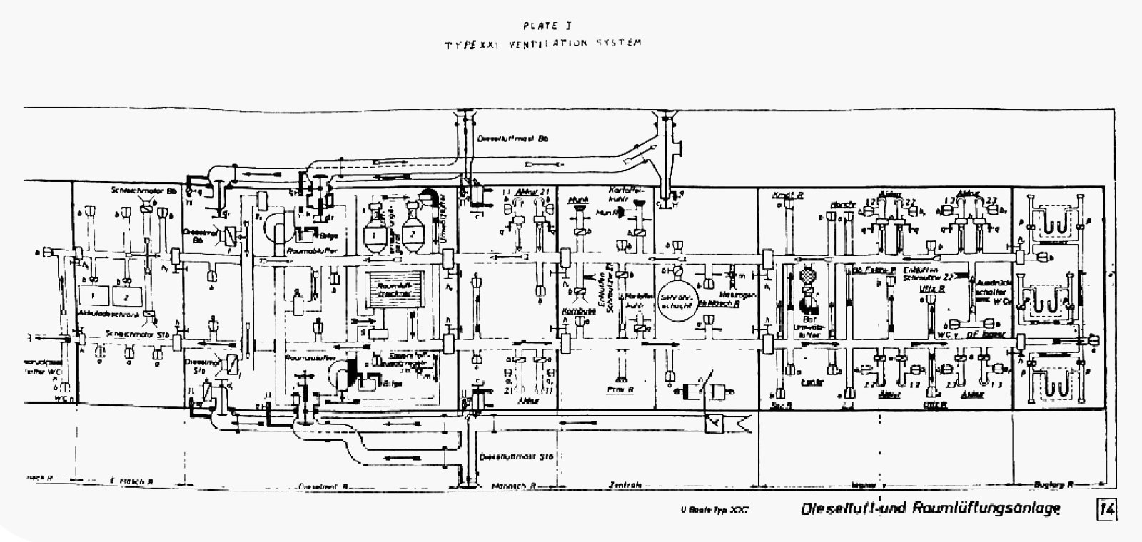
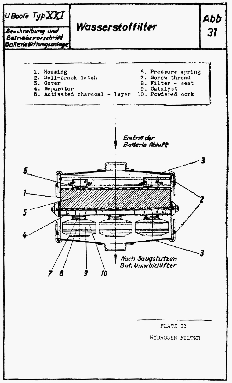
|
|||||
FORMER GERMAN SUBMARINE TYPE XXI |
|||||
INSULATION AND LAGGING |
|||||
SUMMARY |
|||||
| The amount of insulation provided in this type of vessel is reduced from that in previous classes. The amount and type of lagging remains unchanged. | |||||
| The use of cork is confined to the refrigerator and cool room in this type of vessel. Where installed the cork is covered by zinc sheets soldered at the joints. | |||||
| The refrigerator insulation is computed on the following basis of heat transfer: | |||||
| Deep freeze - 10 heat units (WE) per sq. meter per hr. | |||||
| Potato locker - 20 " " " " " " " | |||||
| Both the above are rated for an ambient temperature of 95° Fahrenheit, with an interior temperature of -2°F. | |||||
| Comments remain unchanged from those on the 9C report. | |||||
July, 1946 |
|||||
PORTSMOUTH NAVAL SHIPYARD, PORTSMOUTH, N. H. |
|||||
- 1 - |
|||||
|
|||||
FORMER GERMAN SUBMARINE TYPE XXI |
|||||
MACHINERY PLANT |
|||||
SUMMARY |
|||||
| The hull form, and machinery and battery arrangement on the type XXI have been designed for high sustained underwater speeds. This has been accomplished at a definite sacrifice in surface operating characteristics, notably in maximum sustained speed and in ship handling. | |||||
| The electrical part of the plant - the main motors, the creeping motors and the battery - has proved most satisfactory. However, major difficulties arising from the original diesel engine installation have reduced the satisfactory output to approximately 40% of designed performance and resulted in a serious unbalance in the machinery setup. | |||||
April, 1946 |
|||||
PORTSMOUTH NAVAL SHIPYARD, PORTSMOUTH, N. H. |
|||||
- 1 - |
|||||
|
|||||
MACHINERY PLANT |
|||||
| 1. INTRODUCTION | |||||
| Numerous conflicting statements have been made in various existing documents concerning the propulsion characteristics for this type of vessel. This report will attempt to correlate the available information and present as accurate a determination of the design and operating characteristics as is presently possible. German test data taken from actual runs over the measured mile and given in "Tests for Type XXI Submarines" (Typ-Erprobungsplan für U-Boots - Typ XXI) is used to substantiate views expressed in this report. | |||||
| 2. GENERAL DESCRIPTION | |||||
| The machinery plant on the type XXI submarine is built around a geared drive propulsion arrangement, on each of two shafts, as shown on plate I. | |||||
| The basic design (on which German trial data is available) incorporated a large battery of 372 cells, two 2470 HP (2500 PS) main motors, two 111 HP creeping motors and two supercharged 1970 HP (2000 PS) diesel engines. The main motor and diesel engine on each side are separately geared to the main shaft while the creeping motor is connected to it by a V-belt drive. Adequate clutches are provided to give maximum flexibility in the use of this arrangement. | |||||
| On trial runs the propulsion motors developed their rated power. When using the main motors, submerged speed in excess of 16 knots were obtained. It should be possible to maintain this speed during a one hour battery discharge. Surface and submerged speeds up to 6 knots have been obtained when running on the creeping motors. The cruising range based on one battery discharge is 365 miles at 5 knots or 110 miles at 10 knots. | |||||
| The diesel engines, on the contrary, have proved a major weakness in the vessel's design. On actual trials the output was limited to 1700 HP (15 knots) by excessive exhaust gas temperatures. Furthermore, the exhaust driven supercharger when used during snorkelling operations proved hazardous and was subsequently removed. The diesel without supercharger is able to operate only with snorkel cams in, with a | |||||
- 2 - |
|||||
|
|||||
| resultant limiting output of 850 HP (12 knots) before excessive exhaust temperatures are reached. As it is necessary to furnish approximately 1200 HP for 4 hours to the generators for charging each of the two batteries at the normal charging rate, the time required for a full charge is excessive. This necessarily places a major handicap on the vessel's operation and decreases the value of the higher submerged speeds. | |||||
| The excessive number of clutches required for this arrangement in order to provide the flexibility desired is a further disadvantage. Continued upkeep on these and their associated synchronizing gear is necessary and much care in operation is required. Also, with the installed arrangement of clutches (See Plate I) it is necessary when using a diesel for propulsion alone to rotate in addition to the main shaft the main motor reduction gear and armature. However, it is readily possible with this setup to put additional motor power on the main shaft to augment the diesels. | |||||
| Tests show a favorable surface propulsion characteristic existing between 16 - 18 knots. The horsepower vs speed curve flattens out appreciably over this range - on actual test an increase in 1126 HP brought about an increase in surface speed from 15.11 to 18.08 knots. This top speed has been attained with the use of the main motors running at full power, or with the main motor boosting the diesel engine while the latter is running at its highest output. In this latter instance, the batteries furnished current for the main motors and auxiliaries at a 6-hour discharge rate. | |||||
| The creeping motors furnish a valuable addition to the propulsion setup. They not only give the desirable quiet operation during evasion tactics, but also furnish valuable surface and submerged propulsion while utilizing the diesels for charging batteries. The fact that they can be operated on 120 V permits a high propulsion efficiency over their entire speed range with a resultant reduced fuel consumption. | |||||
| Compared with U.S. designs, a very small number of auxiliaries have been installed for use with the main propulsion units. To take care of special contingencies, several of the pumps provided are set up for use on several different systems. This is particularly true of the various hand pumps. Blank couplings exist on all systems permitting use of flexible hose connections in emergencies. This flexibility in use of pumps can result in contamination of systems and is not recommended. | |||||
- 3 - |
|||||
|
|||||||||||||||||||||||||||||||||||||||||||||||||||||||||
| 3. INDIVIDUAL COMPONENTS | |||||||||||||||||||||||||||||||||||||||||||||||||||||||||
| Designed and actual performance data on the various units are summarized below: | |||||||||||||||||||||||||||||||||||||||||||||||||||||||||
| a. Diesel Engine | |||||||||||||||||||||||||||||||||||||||||||||||||||||||||
|
|||||||||||||||||||||||||||||||||||||||||||||||||||||||||
| b. Main Motor | |||||||||||||||||||||||||||||||||||||||||||||||||||||||||
|
|||||||||||||||||||||||||||||||||||||||||||||||||||||||||
| c. Silent Motor | |||||||||||||||||||||||||||||||||||||||||||||||||||||||||
|
|||||||||||||||||||||||||||||||||||||||||||||||||||||||||
|
|||||||||||||||||||||||||||||||||||||||||||||||||||||||||
- 4 - |
|||||||||||||||||||||||||||||||||||||||||||||||||||||||||
|
||||||||||||||||||||||
|
||||||||||||||||||||||
| * Includes Vulcan Coupling | ||||||||||||||||||||||
|
||||||||||||||||||||||
| 4. CONCLUSIONS | ||||||||||||||||||||||
| For a submarine that is to operate as a pure submersible, the designed characteristics of the power units used in conjunction with the large battery on the XXI appear properly balanced. In the German design primary consideration was given to supplying main motor propulsion using a minimum of weight and capable of taking the maximum battery output. | ||||||||||||||||||||||
| Further but secondary consideration was given to obtaining diesel engines that would give as much power for charging and propulsion as possible from the remaining allotted machinery weights. Had the rather optimistic design ratings of the diesel engines been obtainable on the completed submarine, a satisfactory plant performance would have resulted. | ||||||||||||||||||||||
| However, because of the failure of the diesel engine to meet its designed rating and further, because of the necessity for the removal of the exhaust driven supercharger, a serious weakness in the vessel's operating characteristics has resulted. The main motors and batteries, on the contrary, have successfully operated at their designed ratings with full reliability. This fact, coupled with the low output of the diesels, has created an unfortunate unbalance in the machinery plant. | ||||||||||||||||||||||
- 5 - |
||||||||||||||||||||||
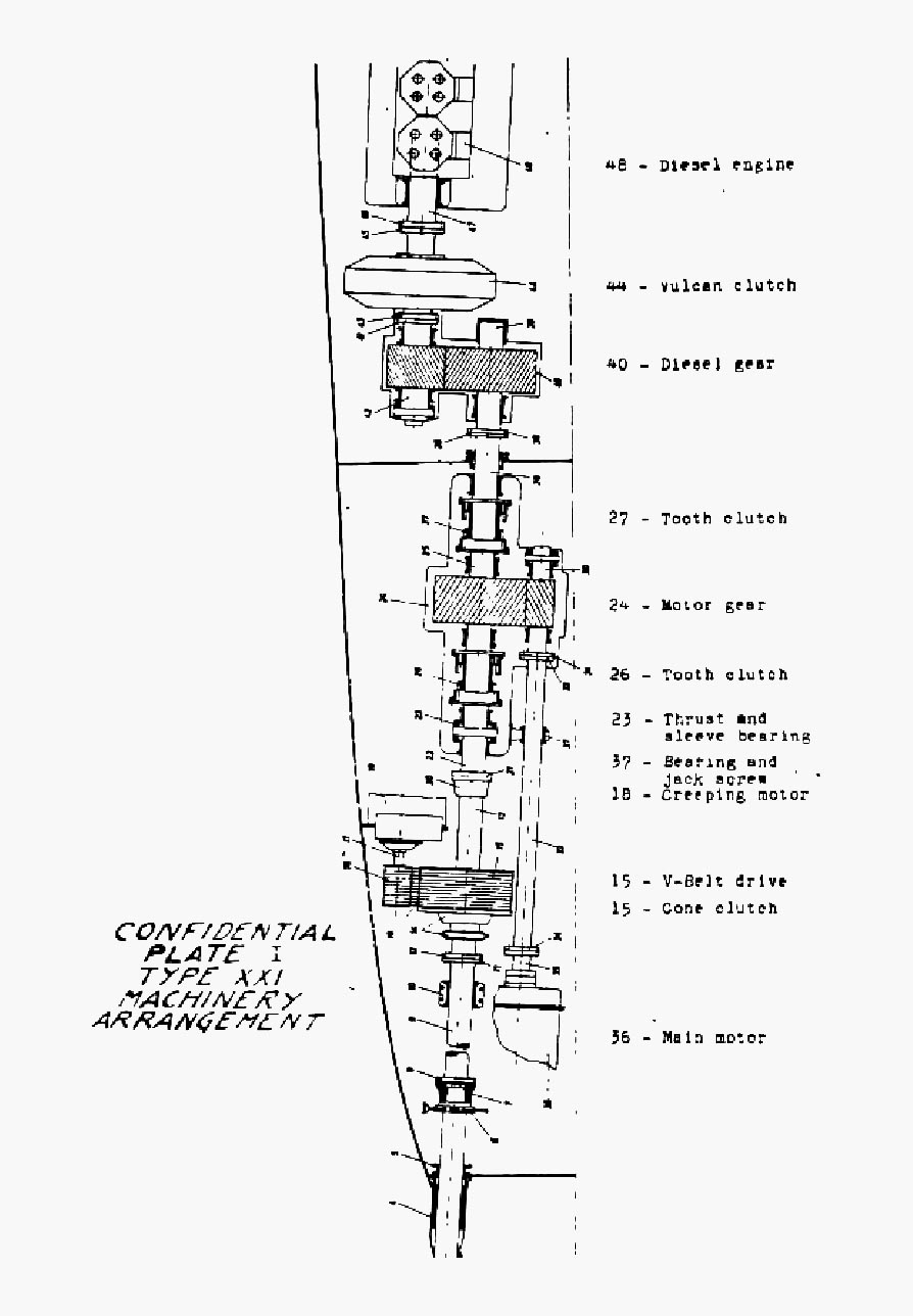
|
|||||
FORMER GERMAN SUBMARINE TYPE XXI |
|||||
DIESEL ENGINE INSTALLATION |
|||||
SUMMARY |
|||||
| Two 6 cylinder MAN diesel engines, with salt water cooling, are installed on the XXI. The engines were originally highly supercharged and rated at 1970 HP and 520 RPM. Their rating has subsequently been reduced to approximately 1200 HP and 470 RPM by the removal of the supercharger. The engines are in most all respects similar to the 9 cylinder MAN engines on the IXC submarines. | |||||
| The air induction on the port side is the same as that for the IXC vessel. On the starboard side it has been combined with the ships ventilation and snorkel air intake. The head and hull valves as well as the outboard and inboard piping runs are essentially similar to those on the type IX submarines. | |||||
| The exhaust gas system has been simplified to some extent. The muffler and spark arrestors have been eliminated and the exhaust discharges below the waterline. Hinged type outboard and inboard exhaust valves with self grinding in features have been retained from the IXC installation. Several changes have been made in their design however. | |||||
| A telescopic type of snorkel mast has been installed on the type XXI vessels. Both engines and their associated systems are designed for operation with the snorkel. As this vessel was designed contemplating its installation the piping arrangements, etc. are more satisfactory than are those on type IX and XB German Submarines. | |||||
July, 1946 |
|||||
PORTSMOUTH NAVAL SHIPYARD, PORTSMOUTH, N. H. |
|||||
- 1 - |
|||||
|
|||||
| 1. Introduction | |||||
| The diesel engine installation on the IX C is described in Report 2G-9C-S41-5. Those parts of the XXI installation that are similar for IX C components will not be described in detail in this report. Also, a limited description of the diesel engine will be given as the engine is on test at the Engineering Experiment Station and will be subject to a report from that activity. Attached pumps are discussed under the S group for the systems they serve. | |||||
| 2. General Description | |||||
| The original diesel engine built for the XXI submarine was an attempt to obtain a high powered, light weight and small size diesel engine by removing three cylinders from the MAN engine used on type IX submarines, and adding a higher speed exhaust gas driven supercharger to obtain greater supercharging pressures. Allowable exhaust gas temperatures were raised from 550° C. to 600° C. (1022° F to 1112° F.). The engine as designed was rated at 1970 HP and 520 RPM. However, on shipboard tests these maximum exhaust temperatures were reached between 490 and 500 RPM, which accordingly limited the output to a lower figure. | |||||
| The blower was designed to operate at a top speed of 12,300 RPM, producing 99.2 C.F.S. of air supercharged 8.53 psi. On test the blower met these specifications. | |||||
| The vessels in U.S. custody as well as numerous other type XXI submarines had their supercharger removed. The precise reason for its removal is not known. Whatever it was that caused the Germans to take this drastic step brought about a serious decrease in diesel power available and a resultant serious unbalance in the machinery plant. A possible reason lies in the damage that would be caused to the exhaust gas turbine should it receive a slug of water during snorkel operation. However, the exhaust gas driven blower on the 9 cylinder MAN engine on type IX submarine was not removed when the snorkel was installed, so that this reason for its removal is not conclusive. | |||||
- 2 - |
|||||
|
|||||
| The original diesel engine was provided with an ahead and a snorkel cam but no reversing cam. The ahead cam was not changed upon removal of the supercharger with the result that the engine could only be operated on the snorkel cam setting. The designed rating of the engine operating in this manner is 1180 HP at 470 RPM. This rating has been reached during trials of one of the vessels in US custody but in so doing exhaust temperatures exceed the allowable maximum. | |||||
| The starting, throttling and cam shifting arrangements on the XXI diesel engine are similar to those on the 9 cylinder MAN on the type IX submarines. Also, pistons, valves, ejectors, attached pumps, and associated gear are for the most part interchangeable with the corresponding 9 cylinder engine parts. | |||||
| The air induction piping has little change from the IX C design. The outboard main induction valves are placed within the after section of the faired conning tower and bridge structure. Air intake slits and louvers are built into the faired structure to provide the necessary supply of air to the valve. These louvers act as baffles to deflect any water taken on with the air downward and away from the air intake. The port induction is used only for engine air supply when on the surface, while the starboard induction line is used for engine and ship's ventilation air supply when submerged. A lead-off line to the ventilation air supply is located just below the ventilation fitting. A slight change in design to both the outboard and hull induction valves has been made. The changes in both cases have been on the hull fittings and not in the valve proper and are unimportant. Although the sketch and the instruction books for the XXI indicate that the outboard valve is provided with hydraulic operation, it was not built into the vessel. | |||||
- 3 - |
|||||
|
|||||
| The exhaust gas system has been changed to conform to a different operating concept with this type of vessel. The importance of noise reduction during surface operation was evidently considered much reduced from previous concepts. This naturally led to a simplification in the exhaust gas piping by the elimination of the muffler and spark arrestor, and by provision for underwater discharge of the gases. A very slight, but negligible increase in back pressure is required to overcome the slight water head and care must be maintained when starting the engines to prevent flooding. However, it is presently an operating practice on US submarines to delay opening the outboard exhaust valve until the engine has started so as to remove water from the exhaust line. | |||||
| The inboard and outboard exhaust valves have some improvements in design over former types. They both have independently removable discs and seats so that new disc and disc inserts can be installed without removing the valve from the vessel. Also, the inboard valve operates about a 45° arc in each side of the vertical, and is no longer counterweighted; the outboard seats with the force of gravity instead of opposed to it as on the type IX vessels. Both valves have the disc rotating arrangement used on earlier German designs. However, in spite of their improvements, extensive overhaul of the exhaust valves on the U-2513 and U-3008 indicates that they are still far from satisfactory. The high temperatures to which these valves have been subjected have not only brought about necessity for removal of disc and seat bearing surfaces, but also have caused an excessive amount of warping of the valve body. | |||||
| The differences in snorkel installation on the XXI over that on type IX and XB vessels are for the most part related to the mast installations. The telescopic mast on the XXI imposed different problems in design. The teardrop cross section was dropped and independent but interconnected air intakes and exhaust cylinders were used. The air intake part of the mast has a float type valve at the top and a gear rack attached to one side. The rack meshes with a pinion that is, in turn, driven by an air motor within the vessel. (The air motor is not satisfactory as an excessive amount of time is required to raise the mast.) At the bottom | |||||
- 4 - |
|||||
|
|||||
| of the air mast is a machined cylinder of slightly greater diameter than the rest of the tube. The air outlet opening is in the middle of this machined section. When the mast is in the raised position two rubber gaskets (similar to those used for German periscope packing) with doughnut type inserts, form a seal on the machined surface above and below the air outlet. The gaskets are attached to a housing built on to the top of the pressure hull through which the mast passes and are designed to be tight against external pressure. Two bearings are in this housing to support the mast. The exhaust cylinder on the mast slides within a fixed cylinder secured to and passing through the pressure hull. A gas tight seal between the cylinders is provided by a rubber gasket that is secured to the flanged upper surface of the stationary tube. The exhaust gas pipe from the engine room is secured to the stationary cylinder. When the mast is raised the port formed by this fitting is uncovered. The exhaust opening at the top of the snorkel mast has been considerably simplified from earlier designs. The deflectors used to direct the gasses away from the intake have been eliminated so that the gasses pass directly out of the mast through elongated slits. When the snorkel mast is lowered it houses in a free flooding well that passes through the pressure hull to the keel. | |||||
| 3. Conclusions | |||||
| The attempt by the Germans to provide a high powered, small size diesel engine for the proposed operation of the XXI submarines that could use interchangeable parts from the 9 cylinder MAN engine proved a failure and created a serious weakness in the vessel as finally delivered. The forced removal of the exhaust gas driven supercharger from the engine decreased the useful output of the engine by nearly half the original designed rating. Furthermore, the engine, on test, both with and without the supercharger, was limited in output below designed ratings by excessively high exhaust temperatures which exceed those permitted in US submarine practice by 350° F., have created trouble in all exhaust valves as they are not suitably designed to take this temperature. | |||||
- 5 - |
|||||
|
|||||
| The omission of the muffler from the exhaust system eliminates a prevalent source of trouble, both as regards maintenance and design, from the vessel. This omission is considered sound practice for the XXI submarine inasmuch as this vessel was not designed with the concept of any prolonged or high speed surface running when in enemy controlled waters. | |||||
| At the present state of development it is believed that the folding type of snorkel holds a slight advantage over the telescopic type. Although the former takes up considerable space within the superstructure when housed, it has a more satisfactory hoisting arrangement and has simpler and more satisfactory seals against salt water entrance. The well within the ship on the XXI takes up valuable space and from a strength standpoint forms an undesirable type of fitting passing through the pressure hull. However, numerous possibilities present themselves for improvement in the XXI design, either through changes in the present system wherein a free flooding well is used, or by the installation of a type that can be housed within the pressure hull without resort to a pressure proof well like a periscope. | |||||
- 6 - |
|||||
|
|||||
FORMER GERMAN SUBMARINE TYPE XXI |
|||||
MAIN REDUCTION GEARS |
|||||
SUMMARY |
|||||
| Two sets of helical type reduction gears for use with the main motors and the diesel engines respectively, and one set of V-belt drives for use with the creeping motors are installed on the XXI. Previous types have had direct drive propulsion units with no gears or belts. Disregarding space considerations, the arrangement of the reduction gears appears unnecessarily complicated. | |||||
| Although considerable maintenance and adjustment is required on the V-belt pulley drives, they provide the desired quiet transmission of power from the creeping motor to the main propelling shaft. | |||||
April, 1946 |
|||||
PORTSMOUTH NAVAL SHIPYARD, PORTSMOUTH, N. H. |
|||||
- 1 - |
|||||
|
||||||||||||||||||||||||||||||||||||||||||||||||||||||||
MAIN REDUCTION GEARS |
||||||||||||||||||||||||||||||||||||||||||||||||||||||||
| 1. INTRODUCTION | ||||||||||||||||||||||||||||||||||||||||||||||||||||||||
| Considerable detailed information on German reduction gear design and manufacturing practices is contained in NavTechMisEu Technical report 357-45. In this report only a general coverage of the subject will be made to analyze the design features of the reduction gears on the Type XXI. | ||||||||||||||||||||||||||||||||||||||||||||||||||||||||
| 2. GENERAL DESCRIPTION | ||||||||||||||||||||||||||||||||||||||||||||||||||||||||
| The diesel engine and main motor reduction gears are shown on Plates I and II respectively. Specific data on these gears is listed below: | ||||||||||||||||||||||||||||||||||||||||||||||||||||||||
|
||||||||||||||||||||||||||||||||||||||||||||||||||||||||
| Oil pressure at 1.5 "atu" (approx. 21 psi) is used for lubrication. This is furnished for both gears by a standby gear oil pump prior to running, and by an attached pump on the main motor pinion shaft when the gears are in | ||||||||||||||||||||||||||||||||||||||||||||||||||||||||
- 2 - |
||||||||||||||||||||||||||||||||||||||||||||||||||||||||
|
||||||||||||||||
| operation. | ||||||||||||||||
| The thrust of the main gears is taken by thrust shoes that bear on the forward and after surfaces of the gears. The pinion thrust is taken by thrust collars on the pinion shafts. A separate thrust collar to restrict movement of the Vulcan coupling is attached to the inner pinion shaft of the diesel reduction gear. | ||||||||||||||||
| The V-belt drive is shown on plate III. Twelve individual leather V-belts are used. The tension of these belts can be readily adjusted. Considerable care is required in order to maintain equal tension on all belts under varying loads, and after prolonged periods of running. Insufficient belt tension and improper condition of the pulley surfaces can result in slippage of the belts, at time producing excessive noise. The V-belts normally remain idle (creeping motor clutch disengaged) when using propulsion from the main motor or the diesel engine. Specific data on the design of this drive is listed below: | ||||||||||||||||
|
||||||||||||||||
| 3. CONCLUSIONS | ||||||||||||||||
| The main reduction gears are standard in nature and offer nothing unique in their design. Herringbone gears are considered more satisfactory than the helical gears used on this type. Also, it would appear that both speed reductions could have been obtained in one gear with no loss in flexibility or propelling characteristics. | ||||||||||||||||
| The V-belt drive employed for the creeping motor is a satisfactory means for transmitting a low amount of power with a minimum of noise. However, considerable maintenance is required to retain maximum quiet power transmission. | ||||||||||||||||
- 3 - |
||||||||||||||||

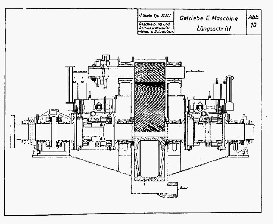
|
|||||
FORMER GERMAN SUBMARINE TYPE XXI |
|||||
SHAFTING AND BEARINGS |
|||||
SUMMARY |
|||||
| A necessary complex shafting coupling arrangement has resulted from the geared drive propulsion setup on the type XXI submarine. On each of the two shafts, in addition to the normally required shaft brakes and main thrust bearing, there are two pneumatic-hydraulic operated jaw clutches for use with the diesel engine and main motor, one cone type friction clutch for use with the silent motor, and a vulcan coupling for use as a vibration dampener. A shaft synchronism indicator and an interlocking device between the main and creeping motor couplings add to the complexities of this setup. | |||||
| A "Huhn carboplan" stern tube seal, similar in principle to the "Syntron Seal" (installed experimentally on the SS 489), is used on this type of vessel. | |||||
May, 1946 |
|||||
PORTSMOUTH NAVAL SHIPYARD, PORTSMOUTH, N. H. |
|||||
|
|||||
SHAFTING AND BEARINGS |
|||||
| 1. INTRODUCTION | |||||
| NavTechMisEu technical report No. 303-45 entitled, "Submarine Main Propulsion Equipment and Arrangement" gives information and plates relative to the shafting arrangements on the type XXI submarines. This present report will not go into any detail on any shafting particulars where already adequately covered in the above-mentioned document. | |||||
| 2. GENERAL DESCRIPTION | |||||
| The shafting layout is shown on plate I under group S40. This plate is self explanatory. The two jaw clutches shown are operated by either power or hand. When in power operation an air on oil cylinder in combination with a hydraulic cylinder and piston is used. The creeping motor friction clutch is operated by hand. The creeping motor friction clutch is operated by hand. The interlocking device between it and the main coupling prevents it from being engaged when the main coupling is engaged. | |||||
| The hydraulic "vulcan" coupling is used only as a shock absorber, preventing the transmission of instantaneous forces from the diesel engine to the reduction gear teeth, as well as reducing power surges to the diesel engine resulting from rough surface operating conditions. No provision is made for rapid dumping of the oil from the coupling, thereby limiting its use. The diesel jaw clutch (located forward of the main motor reduction gear) is used for disengaging the diesel engine from the propulsion shaft under all operating conditions. It has a tendency to stick when thrown with a load on it from either the diesel engine or from the propeller drag. However, information obtained from U.S. operating personnel indicates that this has not given very much trouble to date. | |||||
| The two jaw clutches can only be engaged when the driven and driver shafts are in synchronism - the device for indicating this state is described in the NavTech report mentioned in the introduction. | |||||
| The clutch operation is such as to give the following power combinations on each propeller shaft: | |||||
| a. power on the shaft from the main engine, with the main motor idling. | |||||
- 2 - |
|||||
|
|||||
| b. power on the shaft from the main engine augmented by the main motor. | |||||
| c. power on the shaft from the main motor, with the main engine stopped. | |||||
| d. power on the shaft from the creeping motor, with the main engine and main motor stopped. | |||||
| e. power on the shaft from the creeping motor, with the main engine and main motor operating as a generator unit not connected to the propeller shaft. | |||||
| In addition to the individual thrusts incorporated on the main and pinion gear shafts of both reduction gears, a propeller thrust is installed just aft of the main coupling on the propeller shaft. The main thrust is pressure lubricated and does not have a built-in cooling system for the lubricant as on previous German submarine types. | |||||
| The shafting line runs at an angle of 3°12' to the centerline in the horizontal plane. This comparatively large angle is necessary in order to obtain sufficient room outboard of the main shaft for the main motor and its reduction gear. The shafting line crosses the centerline approximately 11 feet forward of the c.g. (when submerged) resulting in a reverse moment arm of approximately 10". In the vertical plane the shafting line runs at an angle of approximately 0°40' to the base line. The projected line passes about 1 to 1.5 feet below the c.g. (submerged). | |||||
| One strut and one stern tube bearing are installed on each shaft. The distance between centers is approximately 21.7 feet. The bearings are inlaid with either lignum vitae or a type of phenolic material. When the former is used, the lower third of the bearing is with end-grained wood and the upper two thirds is with flat-grained wood. The strut bearing surface is 27.6 ins. long, while the surface of the stern tube is 23.6 ins. long. | |||||
| The stern tube packing gland is of particular interest. The installation is shown on plate I. The inboard part is comprised of 5 rings of cotton or flax packing and a standard lantern ring. This can be taken up uniformly with the gearing arrangement shown. The after part of the gland, (8), is denoted as a "Huhn Carboplan" packing. It functions on a similar principle to that employed by the "Syntron" seal. | |||||
- 3 - |
|||||
|
||||||||||||||||||||||||||||||||||||||||||||||||||||||||||||||||||||||||||||||||||||||||||||||
| All parts of this seal rotate with the shaft. The carbon ring on the inboard end forms a seal with the vertical surface of the metallic ring on the outboard end of the flax stuffing box. The rubber ring shown forms the necessary seal between the "Huhn" packing and the shaft. The syntron seal has two vertical bearing surfaces compared with the one on the German seal - however, when operating under submergence pressures only the inboard seal of the former functions, thereby eliminating the need for the two sealing surfaces. For the installation of either type of seal, a removable shaft flange and a tapered bushing surface are required. | ||||||||||||||||||||||||||||||||||||||||||||||||||||||||||||||||||||||||||||||||||||||||||||||
| The U-2513 on a deep dive to 450 feet had practically no leakage from either shaft gland. On this occasion, the flax packing had been taken up slightly to stop surface leakage prior to descending to this depth and required no further adjustment. The continued operation of both the U-2513 and U-3008 should furnish valuable information on the effectiveness and value of this type of seal for stern tubes. | ||||||||||||||||||||||||||||||||||||||||||||||||||||||||||||||||||||||||||||||||||||||||||||||
| 3. INDIVIDUAL COMPONENTS | ||||||||||||||||||||||||||||||||||||||||||||||||||||||||||||||||||||||||||||||||||||||||||||||
|
||||||||||||||||||||||||||||||||||||||||||||||||||||||||||||||||||||||||||||||||||||||||||||||
- 4 - |
||||||||||||||||||||||||||||||||||||||||||||||||||||||||||||||||||||||||||||||||||||||||||||||
|
||||||||||||||||||||||||||||||||||||||||||
|
||||||||||||||||||||||||||||||||||||||||||
| 4. CONCLUSIONS | ||||||||||||||||||||||||||||||||||||||||||
| The complexity of the shafting layout with its numerous clutches and their associated gear makes the maintenance of the units involved extremely difficult. To effect repairs to even some of the smaller units, extensive dismantling is required. However, it is believed that, once accepting the necessity for the power units and reduction gears in the machinery layout, the shafting arrangement is in accordance with U.S. standards. The vulcan coupling is needed to prevent the transmission of excessive vibrating forces to the reduction gear teeth. Although this coupling could be adapted to rapidly disengage the diesel from the main shafting, this feature was not required with the addition of a desirable quick-operating jaw clutch between the two reduction gears. | ||||||||||||||||||||||||||||||||||||||||||
| The installation of the "Huhn carboplan" seal to limit leakage through the stern tube packing is of particular interest. This seal has been backed up with a standard packing gland to insure safety. The feasibility for this type of packing for stern tubes can be more readily determined after prolonged operation of the two type XXI vessels now in U.S. custody. | ||||||||||||||||||||||||||||||||||||||||||
- 5 - |
||||||||||||||||||||||||||||||||||||||||||
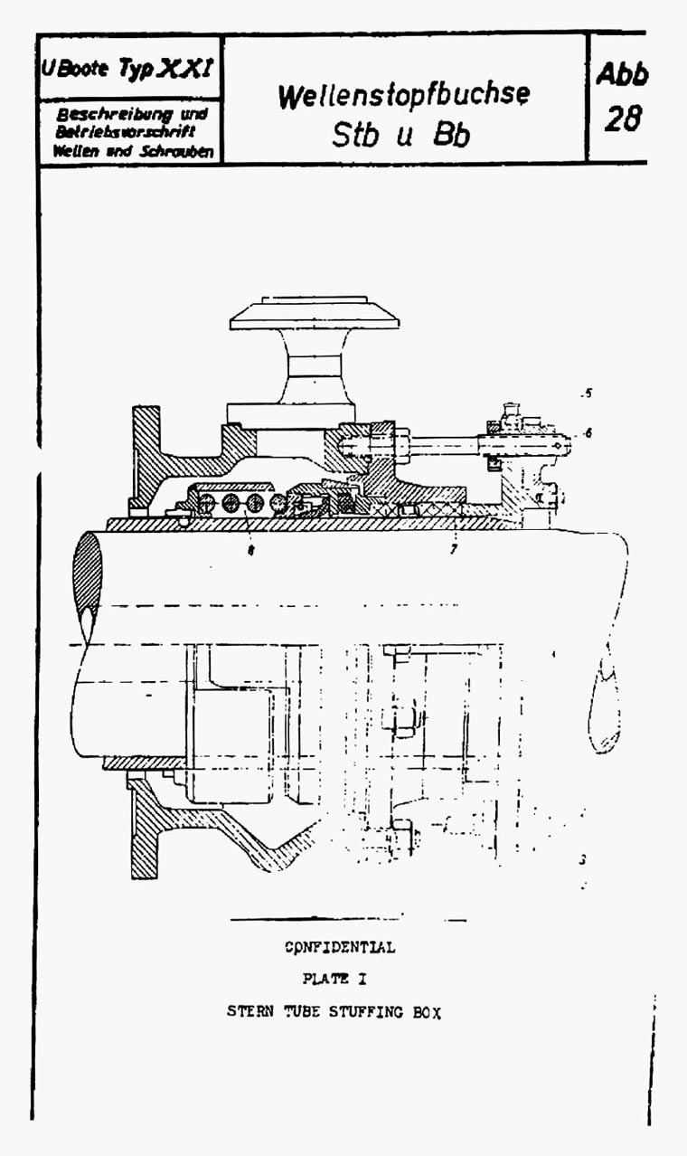

|
|||||
FORMER GERMAN SUBMARINE TYPE XXI |
|||||
PROPELLERS |
|||||
SUMMARY |
|||||
| Twin, 3-bladed, cast steel propellers are installed on the type XXI submarines. They are of standard design and are installed in the normal manner. | |||||
May, 1946 |
|||||
PORTSMOUTH NAVAL SHIPYARD, PORTSMOUTH, N. H. |
|||||
- 1 - |
|||||
|
||||||||||||||||||||||
PROPELLERS |
||||||||||||||||||||||
| 1. INTRODUCTION | ||||||||||||||||||||||
| A detail plan of the propeller used on the XXI submarine has been received from Germany and is in the custody of the Bureau of Ships (Plan No. 5 SCHR 424, "Schiffsschraube"). | ||||||||||||||||||||||
| 2. GENERAL DESCRIPTION | ||||||||||||||||||||||
| The type XXI German submarine is propelled by twin screws of standard design that give a maximum surface speed of 18 knots at 330 rpms and a submerged speed of 16.5 knots at 320 rpms (from German test data). | ||||||||||||||||||||||
| The positioning of the propeller and its interrelationship with the rudder and stern plates is discussed under the S22 section of this report. | ||||||||||||||||||||||
| The propellers are made of cast steel, having a specified tensile strength of 64,000 psi, elastic limit of 31,000 psi and elongation of 22%. This use of steel in lieu of bronze reflects the material shortage existent in Germany during the late years of the war. | ||||||||||||||||||||||
| Information relative to the design and location of the propellers is listed below: | ||||||||||||||||||||||
|
||||||||||||||||||||||
| The propellers are secured to the shaft in the same manner as described for the IX C German submarine. The screws turn outboard when going ahead - | ||||||||||||||||||||||
- 2 - |
||||||||||||||||||||||
|
|||||
| (Attention is called to the fact that several documents in existence stating that they turn inboard are in error.) | |||||
| 3. CONCLUSIONS | |||||
| Except for the fact that the screws are made from a substitute material, the propeller installation and design are standard in nature. | |||||
- 3 - |
|||||
|
|||||
FORMER GERMAN SUBMARINE TYPE XXI |
|||||
LUBRICATION |
|||||
SUMMARY |
|||||
| The forced lubrication system for the diesel engine is laid out in most respects like that on the type IX-C and X-B submarines. An additional attached lub oil pump services the bearings of the exhaust turbine that drives the supercharger when fitted. | |||||
| A forced lubrication system independent of that set up for the diesel engine is used with the remainder of the propulsion arrangement. This system services the main motor bearings, the reduction gears, the jaw clutches, the Vulcan coupling and the main thrust bearings. Two attached pumps furnish the lub oil when the machinery is in operation and a separate detached pump furnishes lub oil for flushing or emergency operations. | |||||
| The transfer system used with older type subs has not been adopted for the XXI. In contrast to the former wide use of manifolds on the type IX and X-B submarines, separate suction and discharge lines run the entire length of the motor and engine rooms; individual suction and discharge cutouts to these lines are located at each tank. | |||||
| The lub oil purifying equipment, although installed as a small compact unit, is of low capacity and does not appear adequate to keep the oil in all the pumps properly purified under all service conditions. | |||||
June, 1946 |
|||||
PORTSMOUTH NAVAL SHIPYARD, PORTSMOUTH, N. H. |
|||||
- 1 - |
|||||
|
|||||
LUBRICATION |
|||||
| 1. INTRODUCTION | |||||
| Report 2G-9C-S45 gives a description of and comments on the IX-C lubricating system. Those parts of the forced lubrication system for the diesel engines and of the purifying arrangements that are similar to the ones on the IX-C will not be covered in detail in this section | |||||
| 2. GENERAL DESCRIPTION | |||||
| In contrast to the requirements on earlier German types, the lubricating systems on the type XXI submarine had to be laid out to provide forward lubrication for not only the diesel engines but also for practically all of the remaining propulsion equipment. To do this two independent systems were set up, a relatively high pressure system with the diesel engines and a low pressure system for all of the remaining equipment. The layout of the former allows IX-C practices while the latter is basically similar to the corresponding part of the lub oil arrangement on U.S. submarines. | |||||
| The diesel engine lubricating system has only two piping changes from the IX-C arrangement. A priming line to the suction side of the pump permits the diesel transfer pump to automatically prime the pump while flushing the system. Also, the absorbent type filter on the suction side of the attached pump has been eliminated as it was on the XB. The pressure bypass relief valve around the attached pump is set at 71.0 psi. The bypass relief to the sump on the intake side of the engine is set to give a lub oil pressure of 37 psi at 400 - 520 engine RPM at the engine. The fact that the cooling water pressure is at all times kept below the lub oil pressure reduces the possibility of salt water leakage into the lub oil. | |||||
| A standard forced lubrication arrangement has been installed for the remaining bearings, couplings and gears that require lubrication. A motor driven pump is set up so as to furnish flushing oil to either or both port and starboard systems from a port or starboard sump. A pressure relief valve is on the discharge side of the pump. | |||||
- 2 - |
|||||
|
|||||
| This pump is not connected to the transfer line, however. The main lub oil service pumps for this system are attached to the main motor reduction gears. They deliver the oil from the sump through a Cuno type knife-edge filter, through a circular tube oil cooler (salt water cooled) to a branch line running to the units to be lubricated. Cutout valves are on this branch line to secure the oil to the diesel reduction gears and to the Vulcan coupling when they are not in use. A second valve is placed in the group leading to the components within the MM reduction gear casing. The units lubricated include the main diesel jaw clutches, the main thrust bearing, the reduction gears and the reduction gear bearings. | |||||
| The lub oil lines leading to the individual main motor bearings have sight glasses and stop valves to permit proper adjustment of flow to the bearings. To provide added flexibility, the port and starboard systems are cross connected. | |||||
| Two features of the XXI setup prevent the flooding of the main motors. The main sumps for this system are built in pressure tight tanks placed below the circular hull, thereby increasing the trim angle that may be taken before a "pressure head" is put on the after main motor bearing; the second and more important feature is in the manner of installation of the main motor bearings. An appreciable air space has been placed between the bearing and the motor housing, and a good housing seal has been provided so that flooding of the motor itself is practically impossible. | |||||
| The lub oil tanks have all been placed in the after part of the vessel. One storage tank is in the after room, two storage tanks in the motor room and a fourth under the forward end of the diesels in the engine room. The engine sumps are placed under the after third of each engine. The reduction gear sumps overlap slightly into the engine room from the motor room. All of these lub oil tanks with the exception of the reduction gear sumps are placed within the bilges of the pressure hull. (It is to be noted that the figure eight hull does not extend aft of the forward engine room bulkhead). | |||||
| The lub oil filling and transfer system is basically similar to the setup on Portsmouth design submarines. A separate suction line runs from the storage tank in the after room to the transfer and hand pumps in the forward | |||||
- 3 - |
|||||
|
|||||||||||||||||
| end of the engine room. Stop-check valves are on the lead-off lines to the engine sumps and stop valves are on the lead-off lines to the remaining tanks. The discharge line runs only to the contaminated oil tank and the four sumps. With this arrangement is is not possible to transfer oil from one storage tank directly to another. The hand lub oil pump and the transfer pump are connected in parallel so that either can be used on the system. | |||||||||||||||||
| The same purifying system with a De Laval oil purifier, attached pumps, and a seawater and lub oil preheaters as used on the IX-C submarines is used on this type. The suction and discharge piping arrangements to the tanks, however, are different. The manifold arrangements have been dropped and individual cutouts are provided at each of the four sumps and the contaminated oil tank. The suction line from the tanks is independent of the transfer piping. The discharge line to the tanks, however, is a common line. | |||||||||||||||||
| The compactness of the purifying unit is particularly noteworthy. The driving motor; purifier pumps and purifier are built integral so as to occupy a minimum of space within the vessel. The pump housing is directly over the motor, and the purifier is placed over the pump housing to form a tight rectangle in cross-section. | |||||||||||||||||
| The contaminated oil system is changed somewhat from that existent on the IX-C. On the XXI the hand lub oil pump is used for handling contaminated oil. A portable hose connection is provided at the pump's suction and on the purifier suction piping leading to the sump and contaminated oil tanks. The discharge can be sent directly to the dirty oil tank through an independent discharge line. Unless care is observed, contamination of transfer and service lines is possible with this arrangement. | |||||||||||||||||
| 3. INDIVIDUAL COMPONENTS | |||||||||||||||||
| a. Diesel lub oil system | |||||||||||||||||
| (1) Attached lub oil pump | |||||||||||||||||
|
|||||||||||||||||
- 4 - |
|||||||||||||||||
|
|||||||||||||||||||||||||||||||||||||
| (2) Lub oil cooler | |||||||||||||||||||||||||||||||||||||
|
|||||||||||||||||||||||||||||||||||||
| (3) Exhaust turbine lub oil pump | |||||||||||||||||||||||||||||||||||||
|
|||||||||||||||||||||||||||||||||||||
| (4) Transfer lub oil pump | |||||||||||||||||||||||||||||||||||||
|
|||||||||||||||||||||||||||||||||||||
| b. Main motor and reduction gear lub oil system | |||||||||||||||||||||||||||||||||||||
| (1) Attached lub oil pump (to MM reduction gear) | |||||||||||||||||||||||||||||||||||||
|
|||||||||||||||||||||||||||||||||||||
| (2) Detached lub oil pump | |||||||||||||||||||||||||||||||||||||
|
|||||||||||||||||||||||||||||||||||||
| (3) Lub oil cooler | |||||||||||||||||||||||||||||||||||||
|
|||||||||||||||||||||||||||||||||||||
- 5 - |
|||||||||||||||||||||||||||||||||||||
|
|||||||||||||||||||||||||||||
| c. Lub oil tank capacities (100% full) | |||||||||||||||||||||||||||||
|
|||||||||||||||||||||||||||||
| d. Lub oil purifying system | |||||||||||||||||||||||||||||
| (1) Purifier | |||||||||||||||||||||||||||||
|
|||||||||||||||||||||||||||||
| (2) Preheaters | |||||||||||||||||||||||||||||
|
|||||||||||||||||||||||||||||
| 4. CONCLUSIONS | |||||||||||||||||||||||||||||
| Except for the inadequate capacity of the purifying arrangements, the lub oil systems on the XXI appear well designed and sufficiently balanced to insure proper lubrication of the units serviced under all operating conditions. However, with salt water cooling of lub oil constant care is necessary to prevent contamination of the oil. | |||||||||||||||||||||||||||||
| A noticeable change from earlier German designs is in the elimination of manifolds from the lub oil systems. The simplification and weight saved by the use in lieu thereof of individual tank cutout valves more than balances the added time required to line up tanks to be used, especially inasmuch as all the valves concerned are situated within the main motor and main engine compartments. | |||||||||||||||||||||||||||||
| The compactness of the purifying arrangement is of note, and points the way to possible improvement in the purifying arrangements on U.S. submarines. | |||||||||||||||||||||||||||||
- 6 - |
|||||||||||||||||||||||||||||
|
|||||
FORMER GERMAN SUBMARINE TYPE XXI |
|||||
CONDENSERS |
|||||
SUMMARY |
|||||
| This section is inapplicable and the page is inserted only for record purposes. | |||||
July, 1946 |
|||||
PORTSMOUTH NAVAL SHIPYARD, PORTSMOUTH, N. H. |
|||||
- 1 - |
|||||
|
|||||
FORMER GERMAN SUBMARINE TYPE XXI |
|||||
PUMPS |
|||||
SUMMARY |
|||||
| All pumps are considered under the systems which they serve. As for those few pumps which are specified by the Navy Filing Manual as being treated separately under the heading, the following is the situation. | |||||
| a) Fire pumps - there are no such pumps, the fire main being served by one of the auxiliary drain pumps. | |||||
| b) Fresh Water Pumps - these are small oscillating force pumps, hand operated, of no exploitational interest, and have been considered under the description of the fresh water system. | |||||
July, 1946 |
|||||
PORTSMOUTH NAVAL SHIPYARD, PORTSMOUTH, N. H. |
|||||
- 1 - |
|||||
|
||||||||||||||||||||||||||
FORMER GERMAN SUBMARINE TYPE XXI |
||||||||||||||||||||||||||
PIPING |
||||||||||||||||||||||||||
GENERAL REFERENCE PAGE |
||||||||||||||||||||||||||
| The piping systems appropriate to this group are discussed under their own separate sub-group headings. | ||||||||||||||||||||||||||
|
||||||||||||||||||||||||||
| It will be noted from the foregoing that certain sub-groups under S48 have not been used. This is accounted for by either the absence of such systems, or by the fact that the components discussed are integral parts of other systems discussed under other "S" groups. | ||||||||||||||||||||||||||
July, 1946 |
||||||||||||||||||||||||||
PORTSMOUTH NAVAL SHIPYARD, PORTSMOUTH, N. H. |
||||||||||||||||||||||||||
- 1 - |
||||||||||||||||||||||||||
|
|||||
FORMER GERMAN SUBMARINE TYPE XXI |
|||||
PUMPING AND DRAINAGE SYSTEMS |
|||||
SUMMARY |
|||||
| The drainage system on the XXI submarine is serviced by two rugged reciprocating pumps, one in the pump room and one in the after room, for pumping against heads up to approximately 1000 ft., and one relatively high capacity centrifugal pump for use against moderate discharge heads. Piping layouts were simplified from earlier German designs. | |||||
| The flooding and draining of the auxiliary tanks on the XXI is accomplished by use either of a rapid flooding or fine flooding line. A two-way reading meter in the fine flooding line permits accurate control of quantity flooded or pumped (or blown) to sea. | |||||
| Pumping arrangements for longitudinal trim control are not provided on the XXI as the system used on earlier designs with divided trim tanks has been employed. | |||||
July, 1946 |
|||||
PORTSMOUTH NAVAL SHIPYARD, PORTSMOUTH, N. H. |
|||||
- 1 - |
|||||
|
|||||
| 1. Introduction | |||||
| Information on the trim and drain system installed on the XXI submarine is given in NavTechMisEu Technical Report No. 306-45. This section will further supplement the information contained therein and repeat details only where necessary for clarity. The trim and drainage systems on type IX and XB vessels are covered in the Reports under the corresponding S48-1 group for these vessels. | |||||
| 2. General Information | |||||
| The drainage system on the XXI submarine has been changed considerably from type IX and XB designs; the trimming system, however, has been taken directly from the altered trim system on the IXD2 submarine. (Described in report 2G-9D2-S48-1.) | |||||
| The drainage system on the XXI submarine has been changed considerably from type IX and XB designs, by combining main and auxiliary drain systems into one system, and by the substitution of individual cut-out and control valves for a manifold arrangement. The drainage system as set up has a main suction line running the length of the vessel. All individual bilge, auxiliary tank, & W.R.T. suctions lead to this line. It is noted, however, that individual bilge sumps have not been built into the pressure hull on this class of vessel so that it is difficult to completely dry out any of the bilges. The line is divided in the control room so that the "shallow" and "deep" drainage pumps in the pump room can take a suction from either (or both) forward and after sections of this line. A second "deep" drain pump can take a suction from this line in the after room. Also, to provide emergency service on the drain line, the standby and two attached cooling water pumps in the maneuvering room have a suction connection to it. The two sea connections that are used for normal and fine flooding and blowing of the auxiliary ballast tanks have connections to the suction line of the drainage system. | |||||
| The discharge from the two control room pumps is normally passed either directly to sea or to No. 3 starboard main ballast tank. A separate connection from the common pump discharge leads to one portable hose fitting for use in filling the trim tanks and to | |||||
- 2 - |
|||||
|
|||||
| several additional fittings for use with deck hoses. Also, a connection from the "shallow" drain pump discharge leads to the circulating water main. The discharge from the after room "deep" drain pump leads directly to sea. | |||||
| An additional amount of drainage is provided in the machinery and battery spaces by arrangements independent, to some degree, of the main drainage system. In the battery spaces drainage piping leads from the upper deck to the upper and lower battery well bilges. This piping is normally used with the slaked lime solution for flushing the painted battery well bilges. Special portable hose fittings can be secured to the piping at the upper deck level which fittings, in turn, can be connected to the main drainage suction. These lines may either be used for removing the lime solution after flushing or for emergency drainage service. | |||||
| The special drainage arrangements in the engine and maneuvering rooms are associated with the pressure tight bilge water tank built into the pressure hull under the maneuvering room. This tank, of 264 gals. capacity, is fitted for receiving the water from the maneuvering room bilges and for blowing it either directly to sea or to No. 1 port main ballast tank. No means of pumping it is provided. A large sluice valve connects the engine and maneuvering room bilges so that the engine room may also be drained by means of this pump. | |||||
| The piping arrangements associated with the divided fore and aft trim tanks provide for normal and silent transfer of water by the use of air pressure and for filling or emptying by use of portable hose connections to the drainage system. The trim line is of 3.15 ins. nominal diameter and is tested to 107 psi. | |||||
| The "deep" bilge pumps are designed along the lines of the auxiliary drain and trim pumps on the type IX and XB submarines. The same double-acting type of piston with cross-head arrangement has been retained. However, all parts of the installation have been considerably strengthened to take the increased discharge heads against which the pump is designed to operate. A water ejector (with sea pressure suction) is placed in the suction to the pump in order to increase the suction head. | |||||
- 3 - |
|||||
|
|||||
| This pump was designed to deliver 100 GPM at discharge heads up to 300 meters (985 ft.) but, as pointed out in the Nav. Tech. Report, could only deliver 88 GPM at this head on test. This was the first class of German submarine with drainage pumps that could discharge against pressures greater than those of designed submergence. (The designed discharge head on the XXI corresponds to that of designed collapsing depth). | |||||
| The single stage centrifugal "shallow" drain pump selected for the XXI submarine is identical to the standby circulating water pump in the maneuvering room. The characteristics for this pump are listed under the S48-5 section of the XXI report. This pump provides the vessel with a high pumping capacity (308-440 GPM) at submergences up to 100 feet. This capacity is particularly desirable at shallow submergences to take care of drainage into the vessel during snorkel operation. | |||||
| The drain piping is designed to be used up to collapsing depth. The suction piping is tested at 45.2 psi; the discharge piping is tested at 455 psi for tightness and 570 psi for strength. The main drain line is 125MM (4.93 ins.) in diameter (nominal size). | |||||
| The arrangements on the XXI for the pumping or blowing and flooding of auxiliary tanks are of particular interest. The associated systems have been set up with the intention of obtaining normal buoyancy control by pumping and flooding, either with or without use of the hovering gear (schwebegerate). This flooding is controlled from either of two sea connections, one for fine and the other for rapid flooding. A flow meter that can measure in either direction is on the fine flooding line. The pumping is also set up for fine or rapid control. For rapid pumping, the water is discharged to sea through the main drainage system sea discharge in the control room. For fine control the water is discharged to sea through the fine flooding line and its sea connection (via the above-mentioned meter). A cross connection connects the drain pump discharge line with the fine flooding line. Volume gages are provided for each auxiliary tank so that a ready check on volume pumped or flooded is possible. | |||||
- 4 - |
|||||
|
|||||
| The German designers intended that buoyancy control during evasive action would be attained by a special blowing - flooding technique. One of the auxiliary tanks was to be set up ready for blowing to sea during shallow submergence with an air pressure on the tank of 43-57 psi; a second was to be set up for blowing at deeper submergences with 230-256 psi. air pressure; the third was to be set up for flooding while the fourth was to be kept in reserve and used as conditions dictated. With air pressure already on the tank the noise emitted while blowing the water to sea is considerably reduced and kept below that created during normal pumping operations. (This arrangement parallels that set up for fore and aft trim control with the divided trim tanks.) To provide additional safety when blowing tanks with air differential pressure gages are installed on all auxiliary ballast tanks to show the differences in tank and sea pressures. | |||||
| Several features in the design of the XXI submarine makes this technique more feasible on this type than on other German types, and, to some extent, more than on U.S. submarines. The compression of the hull on the XXI is 680 lbs./100 feet change in depth (Equivalent to 900 lbs./100 feet for U.S. fleet submarines). This is much less than on earlier German types so that the amount necessary to blow to sea for changes in depth is correspondingly decreased. Furthermore the auxiliary ballast tanks are for the most part "under" the vessel so that large quantities of water need to be blown out (or flooded) from any one side tank to bring about appreciable change in list. As a result considerable buoyancy control can be obtained by the above technique without a noticeable change in list. If necessary, however, by originally putting the air on a port and a starboard tank it is also possible to obtain silent list control simply by transferring water athwartships, although, in this case, it would most always be necessary to vent one tank inboard. | |||||
| The quantity that could be transferred silently by the above method is limited both by the reduction in air pressure and by the quantity of water within one tank. However, except under unusual circumstances, this "limited" quantity will be more than adequate to meet weight change demands over long periods of silent running. | |||||
- 5 - |
|||||
|
|||||||||||||||||||||||||||||||||||||||||||||||
| 3. Individual Components | |||||||||||||||||||||||||||||||||||||||||||||||
| Deep drain pump characteristics (designed) | |||||||||||||||||||||||||||||||||||||||||||||||
|
|||||||||||||||||||||||||||||||||||||||||||||||
| 4. Conclusions | |||||||||||||||||||||||||||||||||||||||||||||||
| The drainage system for the XXI submarine is well designed in that it can handle all normal and most emergency drainage requirements for all submergences up to collapsing depths. Some question arises, however, in whether or not the selection of a piston pump is best for use against the high discharge heads. It is believed that a multi-staged centrifugal pump, similar to the US Gould pump in design would have given better all-around characteristics both for shallow and deep submergences, although certain features such as ruggedness and attainable suction head favor the reciprocating pump. | |||||||||||||||||||||||||||||||||||||||||||||||
| The installation of a system to obtain fine control of buoyancy in addition to the normal rapid, coarser control, was possibly necessary for creeping speed operations. The XXI becomes very tender and difficult to control at low submerged speeds. However, this fine control could have readily been obtained without resort to an additional sea connection. | |||||||||||||||||||||||||||||||||||||||||||||||
| The techniques for silent blowing of the variable ballast tanks has some merit. However, the added complexity in tank construction and piping layouts as well as the several disadvantages arising from the necessary setup, appear to counterbalance the limited need for the system on heavy hull submarines. | |||||||||||||||||||||||||||||||||||||||||||||||
- 6 - |
|||||||||||||||||||||||||||||||||||||||||||||||
|
|||||
FORMER GERMAN SUBMARINE TYPE XXI |
|||||
CIRCULATING WATER SYSTEMS |
|||||
SUMMARY |
|||||
| The circulating water setup on the XXI consists of a circulating water main and independent systems in the maneuvering room, engine room and control room. Each of the 3 systems can either supply circulating water to the main or receive from it. An emergency tie-in is also provided for reciprocal service with the main drainage system. | |||||
| The circulating water main and the systems within the maneuvering room and control room, with the single exception of that part connected to the electric air compressor, are designed to be operated at deep submergence. Individual units connected to the main and the diesel engine components within the engine room are not designed to withstand this pressure. | |||||
June, 1946 |
|||||
PORTSMOUTH NAVAL SHIPYARD, PORTSMOUTH, N. H. |
|||||
- 1 - |
|||||
|
|||||
CIRCULATING WATER SYSTEMS |
|||||
| 1. Introduction | |||||
| Those parts of the IXC circulating water systems, described in Report 2G-9C-S48-5, that have been adopted on the type XXI submarine will not be discussed in detail in this section. | |||||
| For some of the components within the systems test pressures as originally specified in the building specifications were not attainable and had to be consequently reduced. The test pressures listed herein will be those obtained from latest available information. | |||||
| 2. General Description | |||||
| Much additional cooling service is required of the circulating water systems on the type XXI submarine beyond that required on the IXC. Consequently considerable change on system layouts has been made. | |||||
| Three independent systems, each of which has its own individual sea suction and discharge, have been set up to service most of the equipment. The remaining units receive cooling water from a circulating water main that runs from the control room to the after end of the maneuvering room. (The main divides into port and starboard lines at the after engine room bulkhead.) The pumps from any of the individual systems as well as the centrifugal drain pump can put pressure on this main. In addition, all units, with the exception of the air conditioning condensers, can be serviced from the main. | |||||
| The system within the maneuvering room services the main motor and the reduction gear components. It is normally set up with the port circulating water pump (attached to the main motor reduction gear) supplying circulating water to the port units, i.e. the gear lub oil cooler, the two main motor air coolers and the stern tube, and with the starboard attached pump servicing the corresponding starboard units. A standby pump is also installed to provide additional or emergency service, and can discharge to either or both circulating water mains. All three pumps can take their suction from a common suction line that connects port and starboard sea suctions, and has a connection to the vessel's main drain. All piping and units | |||||
- 2 - |
|||||
|
|||||
| in the main motor circulating water system are tested to withstand a pressure of 455 psi for tightness and 568 psi for strength. A valve in each circulating water main serves to isolate the main motor circulating water piping from that forward. These valves are normally secured on going to deep submergence. | |||||
| The diesel engine circulating water system is simpler than that on the IXC. The pump discharge manifold has been eliminated and the two attached pumps discharge directly to the lub oil cooler and diesel engine. The two attached pumps have interconnected port and starboard sea suctions. The hand circulating water pump has a suction to this cross connection. Either of these three pumps can also take a suction from the engine room bilges. They have, as well, a discharge connection to the circulating water main. The operating pressure on the system is set at 28 - 35 psi while the test pressure on all inboard parts is limited to 142 psi. | |||||
| The third independent circulating water system has a sea suction in the control room for the three units serviced, and a separate sea discharge in the control room for the compressor and the cold storage condenser and one in the engine room for the air conditioning condensers. The compressor and cold storage units can be serviced by the small circulating water pumps provided for each or by water from the circulating water main. However, the 3 air conditioning condensers can only be serviced by the 3 individual pumps provided. The test pressure on the electric compressor circulating water piping is limited to 213 psi while that for the remainder of the system is increased to 455 psi, permitting its use at deep submergence. | |||||
| The distiller, Junkers compressors, and lub oil purifiers receive circulating water direct from the circulating water main. The piping for these units is not designed to take deep submergence pressures, that for the Junkers is limited to 85.2 psi. | |||||
| Pressure is normally put on the circulating water main by either of the maneuvering room or engine room pumps. The emergency connection to the line from the centrifugal drain pump discharge is in the control room. The test pressures on the circulating water main and its branches, up to the first stop valve on each branch, is 455 psi for tightness and 568 psi for strength. That of the branches outboard of the stop valve is as heretofore specified. | |||||
- 3 - |
|||||
|
|||||||||||||||||||||||||||||||||||||
| 3. Individual Components | |||||||||||||||||||||||||||||||||||||
| a. Attached circulating water pump (diesel) | |||||||||||||||||||||||||||||||||||||
|
|||||||||||||||||||||||||||||||||||||
| b. Attached circulating water pump (reduction gear) | |||||||||||||||||||||||||||||||||||||
|
|||||||||||||||||||||||||||||||||||||
| c. Standby circulating water pump | |||||||||||||||||||||||||||||||||||||
|
|||||||||||||||||||||||||||||||||||||
|
|||||||||||||||||||||||||||||||||||||
| 4. Conclusions | |||||||||||||||||||||||||||||||||||||
| The circulating water systems on the type XXI submarine are provided with extreme flexibility at an undesirable sacrifice of safety. The designers have permitted a desired wide interchangeability in the use of the various pumps within the several circulating water systems and have set up an emergency exchange of service between the pumps in the circulating water and the main drainage system, features which are not possible with the completely independent engine room, maneuvering room and control room systems on U.S. submarines. However, in providing wide flexibility added reliance has been placed upon operating personnel to insure that excessive pressures are not placed on low pressure equipment during deep submergence. The possibility of the pressure arising from either open or leaky valves is greater because of the presence of the necessary interlocking valves between the systems. | |||||||||||||||||||||||||||||||||||||
- 4 - |
|||||||||||||||||||||||||||||||||||||
|
||||||||||||||||||||||||||
FORMER GERMAN SUBMARINE TYPE XXI |
||||||||||||||||||||||||||
SCUPPERS AND DRAINS |
||||||||||||||||||||||||||
SUMMARY |
||||||||||||||||||||||||||
| Deck drains provided are as follows: | ||||||||||||||||||||||||||
|
||||||||||||||||||||||||||
| Bilge drains for equipment remain extensive and complete, as on earlier vessels. | ||||||||||||||||||||||||||
| Tank top drains, as such, are not provided, but tank top drainage is accomplished by providing openings and pathways which will carry the water away although they do not serve this sole purpose. | ||||||||||||||||||||||||||
July, 1946 |
||||||||||||||||||||||||||
PORTSMOUTH NAVAL SHIPYARD, PORTSMOUTH, N. H. |
||||||||||||||||||||||||||
- 1 - |
||||||||||||||||||||||||||
|
|||||
| 1. Comments: | |||||
| It does not appear that the draining of water from the quarters into the battery wells is desirable or necessary in view of the availability of tanks to receive such water. Further, in this type of vessel there is no sump to take a suction from the pump room or battery well, so that water draining into these spaces cannot be evacuated as it should be. | |||||
- 2 - |
|||||
|
|||||
FORMER GERMAN SUBMARINE TYPE XXI |
|||||
SOUNDING TUBES AND VENTS |
|||||
SUMMARY |
|||||
| Sounding tubes and venting arrangements continue to be normal in general, but the installation of sounding tubes in drinking water tanks is retained from earlier types of vessels, and one pair of main ballast tanks is provided with inboard vents for use after blowing in order to offset overcompensation. | |||||
July, 1946 |
|||||
PORTSMOUTH NAVAL SHIPYARD, PORTSMOUTH, N. H. |
|||||
- 1 - |
|||||
|
|||||||||||||||||||||||||||||||||||||||||||||||||||||||||||||||||||||||||||||||||||||||||||||||||
| Sounding and venting connections in this type of vessel are as follows: | |||||||||||||||||||||||||||||||||||||||||||||||||||||||||||||||||||||||||||||||||||||||||||||||||
|
|||||||||||||||||||||||||||||||||||||||||||||||||||||||||||||||||||||||||||||||||||||||||||||||||
| Inboard vents, with sight glasses and mufflers, are fitted to the regulating tank, regulating bunker and MBT 3. Inboard vents are provided as well on all fuel oil tanks and a further inboard vent is provided for the spray shield over the torpedo tube nozzles. | |||||||||||||||||||||||||||||||||||||||||||||||||||||||||||||||||||||||||||||||||||||||||||||||||
| Vents are provided at the high points in fluid piping systems. | |||||||||||||||||||||||||||||||||||||||||||||||||||||||||||||||||||||||||||||||||||||||||||||||||
| Main vents are discussed in the S29 and S49 sections of the report. | |||||||||||||||||||||||||||||||||||||||||||||||||||||||||||||||||||||||||||||||||||||||||||||||||
| Comments: | |||||||||||||||||||||||||||||||||||||||||||||||||||||||||||||||||||||||||||||||||||||||||||||||||
| Applications are normal in all respects. Much greater use is made, in this type of vessel, of separate sounding and venting tubes than in earlier vessels. The provisions of inboard vents on MBT 3 is unusual, and is explained in the General Information book as being installed to permit reventing after blowing when submerged, without showing a bubble on the surface. In the absence of any pressure gauges or other indication of the condition of this tank, it is thought that the arrangement would be of limited value except in an emergency. | |||||||||||||||||||||||||||||||||||||||||||||||||||||||||||||||||||||||||||||||||||||||||||||||||
- 2 - |
|||||||||||||||||||||||||||||||||||||||||||||||||||||||||||||||||||||||||||||||||||||||||||||||||
|
|||||
FORMER GERMAN SUBMARINE TYPE XXI |
|||||
FITTINGS |
|||||
SUMMARY |
|||||
| The descriptive material in the 9C report applies generally to this class of vessel. No exceptions worthy of note have been observed. | |||||
July, 1946 |
|||||
PORTSMOUTH NAVAL SHIPYARD, PORTSMOUTH, N. H. |
|||||
- 1 - |
|||||
|
|||||
FORMER GERMAN SUBMARINE TYPE XXI |
|||||
PIPING |
|||||
SUMMARY |
|||||
July, 1946 |
|||||
PORTSMOUTH NAVAL SHIPYARD, PORTSMOUTH, N. H. |
|||||
- 1 - |
|||||
|
||||||||||||||||||||||||||||||||||||||||||||||
| 1. The valves in this type of vessel have been in part redesigned for higher pressures. The changes are most pronounced on the hull valves. | ||||||||||||||||||||||||||||||||||||||||||||||
| 2. The different types and sizes of hull valves given in the hull closure book (Bordabsperrungen - U Boote Typ XXI) are as follows: | ||||||||||||||||||||||||||||||||||||||||||||||
|
||||||||||||||||||||||||||||||||||||||||||||||
|
||||||||||||||||||||||||||||||||||||||||||||||
- 1 - |
||||||||||||||||||||||||||||||||||||||||||||||
|
|||||
|
|||||
| 3. Of interest is the general reversion to the earlier practice of having hull valves close with pressure. Additional points of interest are the absence of gate valves in connection with hull closures, the increase in the completeness of back-up valve installation, and the substitution of flapper valves for cocks in the voice tube installation. An added note of precaution is the installation of cocks on piping from grease cups to hull fittings. | |||||
| 4. Other evidence of change are apparent in the character of the flange employed to connect hull valves to hull fittings, in the appearance of the yoke on back-up valves, and in the abandonment of shouldered spindles with gaskets on air valves. | |||||
| a. The flange connection which on earlier types of vessel was the common welding flange with multiple bolts, is here changed to the type of flange used in American commercial practice on ammonia lines. The two halves of type have a mating and rather narrow gasket face, outside of which the adjoining (but not fraying) surfaces are beveled away from one another. In plan the flange has a square shape, and the two halves are joined and secured by means of four bolts; one at each corner. Provisions are made to offset the effect of minor misalignment on bolt and nut stressing by means of washers which are spherical segments. | |||||
| b. The yoke on back-up valves is still cast integral with the bonnet, but projects out from the stuffing box, up and back in an oval shape to the spindle nut. It would appear that the type of yoke introduces the possibility of unnecessary concentrations of stress at points on the spindle nut and the stuffing box. | |||||
| c. Hull valves on air lines in this vessel have the normal gland nut, separate gland, and packing found on valves for other systems. This appears to be a retrogression in design, considering the merits of the | |||||
- 2 - |
|||||
|
|||||
| type previously employed. | |||||
| 5. The piping arrangements within the vessel are notable for the reduction in the number of manifolds. Instead, multiple individual valves are employed, connected to give the desired combination of suction and drain connections. Manifolds are retained only on the air systems (including blowing arrangements, torpedo air arrangements and the oxygen system) and on the regulating tank gauge piping. It would be interesting to know whether the absence of manifolds was caused by scarcity of casting facilities or by lack of trust in manifold behavior under shock. | |||||
| 6. The air manifolds remain unchanged in type from earlier vessels. The shouldered spindle, glandless valve is still used. | |||||
| COMMENT | |||||
| Points of interest are the reversion to hull valves closing with pressure, the reduction in number of manifolds and miscellaneous changes which generally are a return to older practice. Valves have been made sturdier to withstand the greater submergence depth of this vessel as compared with that of previous vessels, but no new design details have become evident locally. | |||||
- 3 - |
|||||
|
|||||
FORMER GERMAN SUBMARINE TYPE XXI |
|||||
COMPRESSED AIR PLANT |
|||||
SUMMARY |
|||||
| The air systems installed in this type of vessel are not altered in major particulars from those on earlier vessels, although certain changes have been made to reduce the number of separate lines and the sizes of the manifolds. | |||||
| Compressors, manifolds, valves, piping and operating gear are all of the same general types as those on the 9C and 9D2 vessels. | |||||
July, 1946 |
|||||
PORTSMOUTH NAVAL SHIPYARD, PORTSMOUTH, N. H. |
|||||
- 1 - |
|||||
|
|||||
| General | |||||
| 1. The air systems installation is greatly simplified in comparison with the systems on the XB vessels, and has many of the characteristics of the installations on IXC and IXD2 vessels. | |||||
| Compressed Air Plant and High Pressure Piping Arrangement | |||||
| 1. The compressed air plant consists of two diesel compressors in the engine room, one electric compressor in the pump room, 23 air flasks all located within the pressure hull, a manifold in the control room and interconnecting piping. | |||||
| 2. Each compressor is provided with a separate lead to the air manifold, and in each lead is a water separator and a filter. | |||||
| 3. The two leads from the diesel compressors are arranged to permit them to be connected together, and from this bilge piping section branches are taken off to the three after air banks, to the main engine and diesel compressor starting connections and to the bilge water tank (which in this type of vessel takes the place of the one main ballast tank on the 9C and 9D vessels which was equipped with flood valves.) The branch to the starting air arrangement is supplied with a filter and with two 2920 to 427 psi reducing valves in parallel. Further, the lead from the port diesel compressor has a branch which leads to air bank No. 4 in the magazine, while the corresponding starboard lead has a branch to air bank No. 5 in the control room. | |||||
| 4. The piping from the electric compressor has no branches between the unit and the high pressure air manifold. | |||||
| 5. The manifold is much smaller than that on earlier vessels. No separate leads to air banks are provided, as all leads serve multiple purposes. Connections provided are as follows: | |||||
| a) From the starboard diesel compressor. | |||||
| b) From the port diesel compressor. | |||||
| c) From the electric compressor. | |||||
| d) From the air transfer line. | |||||
- 2 - |
|||||
|
|||||
| e) Two to the low pressure air manifolds. | |||||
| f) To the hydraulic system. | |||||
| g) To the negative tank (in design only, as the negative tank was later abandoned as a design element). | |||||
| h) To the torpedo h.p. air manifold in the torpedo room forward. | |||||
| i) To the mine ejection valve (this does not appear to be fitted to torpedo tubes in available vessels of this type). | |||||
| j) To the high pressure blow manifold. | |||||
| 6. Branches on the piping connections listed above, arranged by the same subheads, are as follows: | |||||
| a) To air bank No. 5. | |||||
| b) To air bank No. 4 with a bridged connection to what was originally the lead to the negative tank, and to the antenna mast. | |||||
| c) None. | |||||
| d) To the Mae West filling connection. | |||||
| e) None. | |||||
| f) None. | |||||
| g) See (b) above. | |||||
| h) To air bank No. 7. | |||||
| i) To air banks No. 6 and 8, and to the normal connections to the high pressure blow manifold. | |||||
| j) To the regulating tank blow manifold. | |||||
| 7. The arrangement of piping permits charging of air banks, operation of the antenna mast and operation of torpedo tubes, when surfaced or snorkeling, even though the high pressure air manifold is not in service. | |||||
| 8. The air volume in the flasks is sufficient to evacuate all main ballast tanks at a depth of 70 meters (230 feet) according to the General Information Book. Total air content of the flasks is 7600 liters (268 cu.ft.). | |||||
| 9. The torpedo high pressure air manifold receives air from the high pressure air manifold either directly or via the line to the mine ejection valve, and has connections, to the windlass motor, to the torpedo charging connections, to the impulse flasks port and starboard, to the torpedo ventilating fittings and the torpedo test connections. | |||||
- 3 - |
|||||
|
|||||
| The one to the windlass operated by way of a regulating valve and relief valve, as the maximum operating pressure of the windlass motor is 85 psi. | |||||
| Low Pressure Air System | |||||
| 1. The low pressure air manifold is supplied by two lines from the high pressure air manifold, one of which has a 2920 to 171 psi reduction valve and the other of which has a regulating and a relief valve. | |||||
| 2. The manifold has direct connections as follows: | |||||
| a) Port trim tanks. | |||||
| b) Starboard trim tanks. | |||||
| c) Pneumatic tool connections forward, torpedo flood and drain arrangements in the torpedo room, forward sanitary blow, and the sea chests forward. | |||||
| d) The vent valve operating gear control valves. | |||||
| e) RDF mast. | |||||
| f) Gyro compass air cooling piping. | |||||
| g) Radar mast. | |||||
| h) Pneumatic tool and sea chest blow connections aft, sanitary blow connection in the after compartments, and operating gear for the main engine and main clutches in the maneuvering room. | |||||
| i) Periscope air fittings, snorkel mast motor, hovering gear (where fitted) and horn. | |||||
| 3. The piping and valve connections to the trim tanks admit air to either half of the forward or after trim tanks, as desired, thereby displacing water to the related half of the trim tanks at the opposite end of the vessel. | |||||
| 4. The low pressure torpedo air arrangements are the same as those on earlier vessels except that stop valves are substituted for the cocks used in earlier vessels at the top of the WRT tanks. The cock arrangement for selecting the flow of air to the torpedo tube or the WRT tank, with the interrelated venting of the opposite tank, is retained. | |||||
| 5. Angle cocks are employed on the sanitary tanks blow and vent line in lieu of valves. | |||||
- 4 - |
|||||
|
|||||
| 6. The sea chest blow arrangements are of the same type as those on earlier vessels. | |||||
| 7. The vent valve operating gear can all be operated simultaneously under the control of a single valve, or the tanks can be operated under the control of cocks as follows: | |||||
| a) Bow buoyancy alone | |||||
| b) MBT 5 alone | |||||
| c) MBT 4 and 3 together | |||||
| d) MBT 2 and 1 together | |||||
| 8. Although the low pressure air system diagram in the sketch book shows operation for the outboard engine air induction valves, port and starboard for the negative flood valves, no such power operations is provided for the air induction valves, and the negative flood valves have been sealed. Power operation is provided however, for the snorkel quick closing valve, via a separate cock adjacent to the ballast tank vent valve operating cocks. | |||||
| 9. The piping to the RDF and radar mast has, in each case a regulating valve, a relief valve, and a cock which admits air either above or below the piston for lowering or raising the mast. | |||||
| 10. The gyro compass cooling line on this type of vessel has a 171 to 7 psi reducing valve in the line with a bypass in which is a regulating valve, and a relief valve. The normal air blast cooling found on earlier types if vessels is retained. | |||||
| 11. The air-oil operation of the main clutch and main engine clutch operating gear found in earlier types is retained. | |||||
| 12. The snorkel hoist motor is a screw type air motor generally similar for the IMO pumps. Admission of air to one or the other end of the pump determines the direction of rotation. Raising or lowering the snorkel is accomplished by a gear on the motor shaft which engages a ratchet on the snorkel mast. A four-way cock controls the admission of air and the venting of the motor. | |||||
- 5 - |
|||||
|
|||||
| High Pressure Blow System | |||||
| 1. This consists of a manifold which receives high pressure air via either of two lines from the high pressure air manifold or from air banks 6 and 8, if the high pressure air manifold is out of service. A regulating valve is installed in each supply line to the manifold, with a pressure gauge and a relief valve. Lines lead from the manifold to the stern buoyancy tank, main ballast tank 1, 2, 3, and 4, and 5, and the bow buoyancy tank, with a stop check valve at the hull opening for each tank. The lines to MBT 1, 3, 3 and 4 divide and supply air to both halves of each of these tanks. Normally all tanks are blown simultaneously under control of the regulating valve, but each tank can be cut off individually at the manifold and at the hull valves. The hull valves are normally locked open. | |||||
| Regulating Tank Blow System | |||||
| 1. This system receives air from a branch on one of the lines connecting the high pressure manifold and the high pressure blow manifold, by way of a regulating valve. Four valves on the manifold connect to lines which serve each half of the regulating tank and the regulating bunker. Transfer of water from one half to the other half of the same tank is accomplished by opening the appropriate valve or valves. | |||||
| Hydraulic System | |||||
| 1. The air line to the hydraulic system connects two air flasks by way of a regulating valve, oil separator and filter, and supplies make-up air to the air flasks which serves as volume tanks on the hydraulic system. | |||||
| Low Pressure (Exhaust Gas) Blow System | |||||
| This is the same as corresponding systems on earlier vessel, with piping from the main engine exhausts via a main blow valve to a manifold from which piping connections lead off to each of the five main ballast tanks. | |||||
- 6 - |
|||||
|
|||||
| Comment | |||||
| All evidence point to the fact that great efforts were made to conserve weight by reducing the size of the manifolds, and by employing multi-purpose piping leads whenever possible. | |||||
| The type of valve used is the same as that on earlier vessels except at the hull, where valves with packed stem glands are substituted for the earlier type. | |||||
| In general the air systems appear to serve their designed purposes satisfactorily. | |||||
| The exhaust gas blow system has the same advantages and disadvantages as that on earlier vessels. | |||||
- 7 - |
|||||
|
||||||||
FORMER GERMAN SUBMARINE TYPE XXI |
||||||||
AUXILIARY TURBINES |
||||||||
BOILERS |
||||||||
UPTAKES AND SMOKEPIPES |
||||||||
BLOWERS (FORCED AND INDUCED DRAFT) |
||||||||
ASH AND COAL HANDLING AND STOWAGE |
||||||||
SUMMARY |
||||||||
| These sections are inapplicable and the page is inserted only for record purposes. | ||||||||
July, 1946 |
||||||||
PORTSMOUTH NAVAL SHIPYARD, PORTSMOUTH, N. H. |
||||||||
- 1 - |
||||||||
|
|||||
FORMER GERMAN SUBMARINE TYPE XXI |
|||||
FUEL OIL STOWAGE AND EQUIPMENT |
|||||
SUMMARY |
|||||
| The fuel oil service system on the type XXI submarine is essentially the same as that on early submarines. However, stowage arrangements and transfer facilities are for the most part peculiar to this class of vessel. The basic compensating system arrangement utilizing salt water niches in each normal fuel tank has been retained as have the inboard venting and testing arrangements for fuel carrying tanks. Otherwise, numerous differences exist both in tankage layouts and in the associated piping. | |||||
| The transfer piping has been simplified in that all manifolds have been eliminated. Also no transfer pump is installed; stand-by or emergency transfer is accomplished through the use of numerous portable hose connections with the hand circulating water pump, both shallow and deep drain pumps and low pressure air. The piping and fittings have been designed to withstand a test pressure of 113 psi, a change from previous practice. | |||||
| Another major difference comes from the fact that all fuel is carried in normal fuel tanks and variable ballast tanks fitted for that purpose. All fuel tanks are outside of the pressure hull and form a part of a complicated interlocking network of external tanks. The tank locations and shapes resulting from the arrangements have brought about added suction and venting difficulties. | |||||
| A complete fuel oil drainage system has been installed. The drainage from all storage tank test and vent connections, relief valve discharges, diesel engines, and gravity tanks passes via the main fuel oil drain piping to the fuel oil sump. | |||||
- 1 - |
|||||
|
|||||
| 1. INTRODUCTION | |||||
| The fuel oil stowage and piping systems as installed on the IX-C submarine are described in detail in report 2G-9C-S55. Only the changes in the corresponding facilities on the XXI will be covered in this report. | |||||
| 2. GENERAL DESCRIPTION | |||||
| The fuel oil system on the XXI submarine was designed to service two 2000 H.P. MAN diesel engines and two Junkers air compressors. The stowage capacity will provide a maximum cruising range of approximately 15,500 miles at 10 knots on two-engines. | |||||
| All of the fuel oil is carried in the 15 normal fuel tanks and the two auxiliary ballast tanks that have been fitted for carrying fuel oil as no fuel ballast tanks are installed. In each case port and starboard tanks are considered as separate tanks. The fuel tanks have been distributed symmetrically outside of the pressure hull to conform to weight and stability requirements. This has resulted in tanks of varying shapes and sizes at various levels with respect to the pressure hull. Each tank has a salt water niche equivalent to 2% of its fuel capacity. | |||||
| The transfer piping has been considerably simplified. Two transfer lines, one port and one starboard, run inboard the length of the vessel and have a cross-connection in the engine room. All tanks have leads with hull and back-up valves to this line. A lead-off runs from the cross-connection to the gravity feed tank via a fuel oil filter and meter that may be by-passed. The filling line is connected into this lead-off line in such a way that the oil received or discharged can be metered if desired. The three portable hose connections on this line and the one on the filling line for use with air pressure add numerous pumping and blowing possibilities to the transfer system in case of emergencies. Both deep and shallow bilge pumps and the hand circulating water pump can be put on the system through these connections. It is possible to pump oil from any tank to the | |||||
- 2 - |
|||||
|
|||||
| gravity feed tank by this means. | |||||
| Arrangements are provided for the necessary testing and venting of the fuel tanks as well as for emergency means to blow them individually. The test and vent lines run from the bottom and top of the tank respectively and have sight gauges on their inboard side. In addition, bleeder lines take off from between the hull and backup valve on the main transfer piping line to the top of the tank. These also have sight gauges on them. The portable air hose fitting lies between two valves on this bleeder line. To blow the tanks, portable hoses are led to these fittings from the pneumatic tool fittings on the low pressure air line. | |||||
| No measuring lines are provided to determine instantaneous oil levels within the various tanks. However, it is possible to keep a close check on tank contents by metering the oil when filling or emptying them. | |||||
| The oil is fed to the diesel through the same gravity tank arrangement as on the IX-C. The only change in the service piping is that the oil for the Junkers compressors comes directly from the main engine service line instead of from an independent service system. | |||||
| The fuel oil drainage arrangement installed forms a comprehensive oil-salvage system. The tank testing, venting and bleeder lines as well as most of the drain lines from safety valves, the gravity feed tanks and the diesel engine run into the "drainage" mains running the length of the vessel. The fuel oil sump tank is considerably larger on this vessel than it is on the type IX submarines. The hand circulating water pump has a direct suction on this tank. | |||||
| A very simple salt water compensating system is used with the fuel oil system. | |||||
| All compensating water piping runs outboard of the pressure hull; no valves are fitted in any of the lines. The compensating water main runs for the most part in the superstructure the length of the vessel. Individual leads then run directly to the small niches in the fuel tanks. | |||||
| 3. NOTEWORTHY CHARACTERISTICS | |||||
| The simplified compensating arrangement using the outboard compensation water piping and individual expansion niches within each fuel tank has particular merit on this class | |||||
- 3 - |
|||||
|
|||||
| of vessel. Inasmuch as this type is to function mainly as a submersible, especially when in an operating area on patrol, the compensating water system and associated fueling arrangements should be designed with this in mind. When on area (and subject to depth charge) the vessel will normally operate submerged either on the motors, or on the diesel engines utilizing the snorkel. When operating the diesel engines on the snorkel, the head box on the compensating system is no longer required. From this standpoint, only an opening to the sea at the bottom of the tank is necessary to bring about the necessary pressure for transfer of oil. However, to take care of expansion and the danger arising from rupture of lines during depth charge, the salt water niche is necessary. In order to permit the system to function when the vessel is operating on the surface, the head box and lines leading to it are also necessary. Furthermore, to insure that oil may be transferred when on the surface, in the event of a casualty to the line leading from the head box to the tanks, emergency pumping means must be provided. This system does not provide the protection to compensating piping afforded by the U.S. system. However, it is to be noted that any casualty to the part of the line that has been placed within the pressure hull on U.S. submarines and that is external to the hull on the XXI would not bring about a disruption of service on the individual tank compensating system when the submarine is operating on the snorkel. In addition, with the individual niches in each tank the possibility that oil slicks will rise by way of the ruptured compensating line is remote. | |||||
| A minor disadvantage arises from the German setup which, however, should not be very difficult to remedy. Whenever it is desired to remove liquid from the tanks extreme difficulty arises. The only way at present to get rid of the water is by pumping through the small testing lines or by blowing through the compensating lines. Pumping takes too long and blowing is nearly impossible as all tanks must be blown simultaneously. When one tank is blown there is no way to keep the water from siphoning back if the air pressure is released. This difficulty has been reported by the Engineer Officer from the U-2513. Several valves (normally locked open) in the compensating line would remedy this condition. | |||||
| The major advantage of a satisfactory outboard compensating system lies in the elimination of hull valves and inner hull piping, both of which form a potential source of danger either through corrosion or depth charge damage. The number of holes through the pressure hull is considerably reduced and the inboard piping in a crowded inner hull is eliminated. Recent U.S. depth charge tests have shown that whereas hull valves still form a source of trouble, compensating water piping leading from the head box to the | |||||
- 4 - |
|||||
|
||||||||||||||||||||||||||||||||
| expansion tank as well as that within the tanks has withstood the tests with no damage, as have all other free flooding lines. | ||||||||||||||||||||||||||||||||
| The disadvantages inherent in the German arrangement are those that would arise from a rupture. In that it is necessary to run the compensating line through the top of fuel tanks, an undesirable practice. Also, if necessary to pump a tank with a ruptured compensating line when operating the diesel engines on the surface, a void is made at the tank top that on diving must again be flooded through the ruptured compensating line. These are not serious disadvantages and can be minimized by proper design. | ||||||||||||||||||||||||||||||||
| 4. INDIVIDUAL COMPONENTS | ||||||||||||||||||||||||||||||||
| a) Fuel tank capacities | ||||||||||||||||||||||||||||||||
|
||||||||||||||||||||||||||||||||
| b) Fuel oil piping | ||||||||||||||||||||||||||||||||
|
||||||||||||||||||||||||||||||||
| c) Fuel oil service pump | ||||||||||||||||||||||||||||||||
|
||||||||||||||||||||||||||||||||
| 5. CONCLUSIONS | ||||||||||||||||||||||||||||||||
| The fuel oil stowage and handling arrangements on the XXI have been, in most respects, further simplified over the arrangements on earlier types. The amount of piping within fuel tanks has been reduced by the elimination of overboard test lines and measuring lines. The permanent piping within the filling and transfer system has been reduced to a minimum by the elimination of manifolds, the | ||||||||||||||||||||||||||||||||
- 5 - |
||||||||||||||||||||||||||||||||
|
|||||
| elimination of a transfer pump, and the resort to portable fittings and hoses for handling emergencies. The service system has also been simplified slightly by the elimination of the separate Junker's service tank and its associated piping. However, some additional piping is required by the extensive fuel oil drainage system installed for this type. | |||||
| This simplification is more readily acceptable when using gravity feed tanks than it would be with the fuel oil service arrangement on U.S. submarines. | |||||
| Except for the minor defect noted in the text, the simplified compensating system arrangement is considered proper for this type of vessel. The system provided continued service during submerged (snorkel) operation for any casualty that may occur to the exposed line in the superstructure. Emergency pumping arrangement furnishes the necessary surface operation. The extensive elimination of hull fittings and interior piping that results makes the simplification warranted. | |||||
- 6 - |
|||||
|
|||||
FORMER GERMAN SUBMARINE TYPE XXI |
|||||
BOILER FEED-WATER EQUIPMENT |
|||||
SUMMARY |
|||||
| This section is inapplicable and the page is inserted only for record purposes. | |||||
July, 1946 |
|||||
PORTSMOUTH NAVAL SHIPYARD, PORTSMOUTH, N. H. |
|||||
- 1 - |
|||||
|
|||||
FORMER GERMAN SUBMARINE TYPE XXI |
|||||
DISTILLING PLANT |
|||||
SUMMARY |
|||||
| The same, low capacity distilling unit installed on the IX-C submarine has been adopted on the type XXI submarine. Only minor changes have been made in the external piping to the unit. However, because of the larger battery, the total capacity of the battery water tanks has been materially increased. Ten individual tanks, four for the after battery and six in the forward battery, are installed. No ready means for filling the tanks is provided. | |||||
July, 1946 |
|||||
PORTSMOUTH NAVAL SHIPYARD, PORTSMOUTH, N. H. |
|||||
- 1 - |
|||||
|
|||||
DISTILLING PLANT |
|||||
| 1. Introduction | |||||
| The distilling plant on the IX-C submarine is discussed in detail in Report 2G-9C-S58. Only the differences that exist on the XXI will be included in this section. | |||||
| 2. General Description | |||||
| The 63.5 gallon per day distilling plant on the type XXI submarine has to furnish replacement fresh water to a crew of approximately 57 men and battery water for the 372 battery cells. From a design as well as heat standpoint, the still should be operated only on the surface. The feed water for the still comes directly from the circulating water main. During submergence the latter is at submergence pressure so the feed water must be throttled in order to prevent rupture of the light tanks and piping leading up to the distiller. | |||||
| The XXI installation has been simplified slightly from the IX-C arrangement by the elimination of the gravity distillate tank. Also, in lieu of a portable hose connection to the battery water tanks, a simple spigot arrangement on the main distillate tank is used. It is necessary to transport the water in containers to the individual battery water tanks. | |||||
| Each of the ten battery water tanks holds 150 liters (39.6 gals.) of distilled water. They are situated between the batteries on the upper battery flats, 4 in the after battery space and 6 forward. | |||||
| 3. Conclusions | |||||
| The same comments made on the IX-C report in regard to the low standard distiller capacity adopted by the Germans apply to a more pronounced degree on the XXI. | |||||
| Little reliance can be placed on the distiller to furnish replacement water both because of its low capacity and because of the limited time when on patrol that the vessel would be on the surface to operate the unit without hazard. | |||||
- 2 - |
|||||
|
|||||
| This limitation in distiller capacity has far reaching effects on the vessel's operation. Even though it is assumed that none of the replacement water would be made available to the crew, it still is not sufficient for the batteries for any normal length of patrol. The total battery water carried is limited to approximately 400 gallons; this reserve would soon be used even in mild climates if U.S. practices were followed (500 gals. every 4 to 10 days are used during patrols, dependent on conditions). The need for conservation is thus drastic. The baffle arrangement in the individual cell ventilation has some effect on limiting the amount of carry over during battery ventilation. However, to reduce the evaporation to required levels, battery ventilation had to be reduced to dangerous levels and the use of ship's ventilation had to be limited. Extreme hardship on the crew would surely result during operation of the vessel in tropical waters and the duration of stay would be limited by the high rates of evaporation from the cells. |
|||||
- 3 - |
|||||
|
|||||
FORMER GERMAN SUBMARINE TYPE XXI |
|||||
REFRIGERATION |
|||||
SUMMARY |
|||||
| A reasonably modern refrigeration system has been installed on the type XXI submarines, with a layout similar to that on U.S. submarines and the basic freon cycle the same as that used on earlier German types. One compressor is used to service all cooling facilities, i.e., the cold storage room, icebox and "potato" cool room. The solenoid operated cutout valves used in the freon cycle are improvements over earlier German designs. | |||||
April, 1946 |
|||||
PORTSMOUTH NAVAL SHIPYARD, PORTSMOUTH, N. H. |
|||||
- 1 - |
|||||
|
|||||||||||||||||||||||||||||||||||||
REFRIGERATION |
|||||||||||||||||||||||||||||||||||||
| 1. INTRODUCTION | |||||||||||||||||||||||||||||||||||||
| The basic refrigerant cycle employed in the type XXI refrigeration system is given in Report 2G-9C-S59. A brief description of the system used on the type XXI highlighting the changes from earlier types in individual design features will be given in this report. | |||||||||||||||||||||||||||||||||||||
| 2. GENERAL DESCRIPTION | |||||||||||||||||||||||||||||||||||||
| A line diagram of the refrigeration arrangement is given on Plate I. The freon cutout switches are so interconnected that freon flow is either to the cold storage room or to the icebox and "potato" cool room. As shown, individual thermostatically controlled expansion valves are used to control the temperatures of the individual rooms. One of the two valves to the cold storage room is set for -18°C to -20°C and the other is set for +2°C to +4°C. | |||||||||||||||||||||||||||||||||||||
| There are several changes in the system incorporated in the XXI over that existent in earlier German designs. The cooling spaces are all adjacent, making it feasible to use the one large compressor rather than the small individual units. However, the layout it such that mechanical selection for cooling of either cold storage or icebox and "potato" cool room is necessary. The old bellows type of expansion valve has been replaced by the diaphragm type as used on present U.S. designs. The freon cutout switches on the XXI were not used on earlier German types and provide a desirable automatic safety feature to the design. | |||||||||||||||||||||||||||||||||||||
| 3. INDIVIDUAL COMPONENTS | |||||||||||||||||||||||||||||||||||||
| 1. Compressor | |||||||||||||||||||||||||||||||||||||
|
|||||||||||||||||||||||||||||||||||||
- 2 - |
|||||||||||||||||||||||||||||||||||||
|
||||||||||||||||||||||||||
| 2. Cooling Rooms | ||||||||||||||||||||||||||
|
||||||||||||||||||||||||||
| 4. CONCLUSIONS | ||||||||||||||||||||||||||
| Although the refrigeration system on the XXI has several improvements over earlier German designs, it is standard in nature and has no particular features that are worthy of further discussion. | ||||||||||||||||||||||||||
- 3 - |
||||||||||||||||||||||||||
|
|||||
FORMER GERMAN SUBMARINE TYPE XXI |
|||||
ELECTRICAL SYSTEM - GENERAL |
|||||
SUMMARY |
|||||
| The electrical plant in general follows the design incorporated in type IX-C40 vessels except for the following: | |||||
| (a) Battery voltage for main electric machines has been tripled. | |||||
| (b) Electrically operated torpedo handling gear has been introduced. | |||||
| (c) Creeping motors have been added for use in lieu of the main electric machines during slow speed silent operation. | |||||
| (d) The size of the hydraulic plant has been materially increased. Planes and rudder are operated hydraulically instead of electrically. | |||||
| (e) An air conditioning plant and a deep freeze unit have been added. | |||||
| Auxiliary power voltage is the same as on type IX C/40 vessels (110-170 V. D.C.) | |||||
March, 1946 |
|||||
PORTSMOUTH NAVAL SHIPYARD, PORTSMOUTH, N. H. |
|||||
- 1 - |
|||||
|
|||||
| 1. Introduction | |||||
| Reference should be made to Report 2G-9C-S60 on the type IXC vessels regarding the electrical plant installed on type XXI vessels. The scope of this report is concerned only with the differences in the two plants. | |||||
| 2. Description | |||||
| Two main electric machines are installed in this type vessel, one port and one starboard. These serve as motors for propulsion and when energized from the battery or as generators for charging the batteries. | |||||
| Split main control cubicles are installed for control of the main electric machines. | |||||
| Two creeping speed motors each connected to its respective propulsion shaft, Port or Starboard, with multiple V-belts, are installed for use when operating under evasive tactics. Split control cubicles provide for power connection either to the related main control cubicle or the related auxiliary power switchboard. When connected to the control cubicle, the power supply voltages vary between 110 and 170 D.C. | |||||
| Two batteries are installed, each consisting of 186 cells from which voltages of 330 to 510 may be obtained. One is considered as a port and one as a starboard battery. These are not normally connected together, but provision is made for a parallel connection by means of a suitable rotary type switch in the Maneuvering Room. | |||||
| Each battery is divided into 3 groups of 62 cells which are installed in separate watertight tanks. The corresponding groups of each battery are located in tanks one above the other. An air circuit breaker is installed between the battery and the main control cubicle in the positive leg only. | |||||
- 2 - |
|||||
|
|||||
| Auxiliary power loads are arranged to be connected to either the port or starboard auxiliary power switchboards. Auxiliaries in the Engine Room and Aft are connected to the Port board, forward of the Engine Room are connected to the Starboard board. Power supplies are obtained for the port board from the upper battery and for the starboard from the lower battery. Provision is made in the Control Room to apply disconnect blocks for the connecting each board to the opposite battery. | |||||
| Auxiliary power supply voltages vary between 110 - 170 volts D.C. and power is obtained by providing each board with a transfer switch to connect the load to any of the three groups of 62 cells of its respective battery. | |||||
| Regulated 110 V. D.C. for lighting, I.C. equipments and various other purposes is obtained thru use of voltage sensitive relay actuated regulators incorporated as part of the auxiliary power switchboards. | |||||
| In order to meet the hydraulic power requirements due to changing from electric to hydraulic control of the steering and diving plane systems, a second hydraulic plant is installed. | |||||
| One electric motor driven air compressor is installed. | |||||
| 3. Conclusions | |||||
| The same conclusions as are contained in report 2G-9C-S60 on type IX-C40 vessels apply to the type XXI vessels with the addition that a wider use of hydraulic power is observed. | |||||
- 3 - |
|||||
|
|||||
FORMER GERMAN SUBMARINE TYPE XXI |
|||||
NOTE: |
|||||
| See section S 63 for discussion of generators. No auxiliary generators were provided on this type of vessel. | |||||
March, 1946 |
|||||
PORTSMOUTH NAVAL SHIPYARD, PORTSMOUTH, N. H. |
|||||
- 1 - |
|||||
|
|||||
FORMER GERMAN SUBMARINE TYPE XXI |
|||||
ELECTRIC POWER DISTRIBUTION |
|||||
SUMMARY |
|||||
| Auxiliary power distribution circuit layout installed on this type of vessel corresponds in general with the circuit layout incorporated in the type IX-C40 vessels. | |||||
March, 1946 |
|||||
PORTSMOUTH NAVAL SHIPYARD, PORTSMOUTH, N. H. |
|||||
- 1 - |
|||||
|
||||||||||||||||||||||||||||||||||
TABLE OF CONTENTS |
||||||||||||||||||||||||||||||||||
|
||||||||||||||||||||||||||||||||||
- 2 - |
||||||||||||||||||||||||||||||||||
|
|||||
| A. DESCRIPTIVE | |||||
| (a) Introduction | |||||
| Reference should be made to Report 2G-9C-S62 on type IX-C40 vessels and to the German Instruction Books "Skizzenbuch Band E Typ 21" (Sketch Book, Band E Type 21) and "Schiffnetz und Verbraucher U Boote Typ XXI" (Ship's Circuits and Auxiliaries U-Boat Type 21) regarding the power distribution circuit installed in type XXI vessels. The scope of this report is concerned only with the differences in the two systems. | |||||
| (b) Description | |||||
| In order to more clearly understand the installation in this type of vessel a knowledge of the battery installation contained in Report 2G-21-S62-4 is necessary. | |||||
| The system provides for connection of the auxiliary power distribution circuit to any of the six pre-divided battery groups. This is accomplished in the following manner. Under normal conditions all auxiliary equipment installed forward of the Engine Room is energized through the forward distribution board located in the control room which by means of a transfer switch can be connected to battery group 1.1, 1.2, or 1.3 while auxiliary equipment in the Engine Room and aft is energized from the after switchboard located in the Maneuvering Room which by means of a similar transfer switch can be connected to battery group 2.1, 2.2, or 2.3. Provision is made to cross connect these power supply circuits by means of disconnect blocks so that the after switchboard can be energized from the number one battery groups or the forward can be energized from the number two battery groups. Double fusing of circuits apt to be in use during a dive or while submerged is not employed as is the case on type X B vessels. | |||||
| Several discrepancies exist between the actual installation and the circuit layouts in the German Instruction Books. These are enumerated as follows: | |||||
| (a) The designed power supply for the auxiliary power distribution boards contemplated use of groups 1 and 3 of each battery. As previously described the auxiliary power switchboards can be energized from any of three groups of each battery. The forward switchboard, number 2, being energized from groups of battery | |||||
- 3 - |
|||||
|
|||||
| number 1. The after switchboard, number 1, is energized from the groups of battery number 2. | |||||
| (b) The designed 120 V power supply for the creeping speed motors (These motors may be operated at 360 V or at 120 V) provided for use of a transfer switch at the motor which permitted connection of the port motor to group 2 of battery 2 or to the after auxiliary power board which as described above permitted connection of the board and hence the port creeping motor to group 1 or 3 of battery 2 whichever is connected to the board at the time. A corresponding circuit was designed for the starboard creeping speed motor, the forward auxiliary power board and the groups of batter number 1. The transfer switches at creeping speed motors are not installed. The motor is connected to its auxiliary power board which in turn is energized as described under (a) above. | |||||
| Several criticisms with regard to location of circuit components are presented. It is to be kept in mind that the disconnect blocks provided for connecting switchboard number 1 to the groups of battery number 1 and of switchboard number 2 to the groups of battery number 2 are not installed under normal operating conditions. | |||||
| (a) The after switchboard, number 1, is located in the Maneuvering Room. The transfer switch and disconnect blocks are located in the Control Room along with the forward switchboard, its transfer switch and disconnect blocks. This same grouping of components exists on type IX-C vessels. In the event of a casualty in way of the control room a possibility of losing all auxiliary power exists. | |||||
| (b) The main fuses between battery groups 1.2 and 1.3 and the transfer switch are mounted in a common fuse box. A similar box exists for battery groups 2.2 and 2.3. Both of these boxes are mounted on the forward side of the forward control room bulkhead practically adjacent to each other. A similar condition exists in the crew's quarters with regard to the fuses from battery groups 1.1 and 2.1. This type installation is considered very poor in that a localized casualty in these areas might well mean complete loss of all auxiliary power at a critical time. | |||||
| (c) Since each creeping speed motor is energized from the applicable auxiliary switchboard, the fuses for the particular motor are mounted in that board. In the case of the port creeping speed motor this is satisfactory | |||||
- 4 - |
|||||
|
|||||
| since it is energized from the after switchboard which is located in the same compartment. However, the starboard creeping speed motor is energized from the forward board located in the Control Room and the circuit's only fuses are located there. In the event these blow during a critical operating period, additional confusion will exist in that either personnel will have to travel from the Maneuvering Room to the Control Room or an additional burden placed on the ship's phone circuit in order to have Control Room personnel make the change. | |||||
| (d) The same criticism stated in (c) for the starboard creeping speed motor is true of the starboard main motor ventilation blowers. | |||||
| (e) In addition to the above criticisms, it is felt that the auxiliary power component layout in this type vessel with regard to accessibility for the necessary operation of the component is inferior to the other types of German submarines being evaluated. This is evidenced by the following examples. In the Engine Room several manual controller mechanisms for auxiliaries are installed outboard of the Main Engines, in a rather constricted area. To operate these controllers it is necessary to clamber on top of the main engines, then while lying on top, to actuate the controller. | |||||
| CONCLUSIONS | |||||
| The same conclusions as are contained in report 2G-9C-S62 with regard to the application of circuit components, practices, design etc. apply to the type XXI vessels. However, in light of the system installed in type X B vessels, it is surprising that some of the more desirable features incorporated in that type vessel are not installed in this later type vessel. The criticisms offered arise not from the German's need to conserve critical materials, but rather from poor planning on his part. | |||||
- 5 - |
|||||
|
|||||
FORMER GERMAN SUBMARINE TYPE XXI |
|||||
SWITCHBOARDS |
|||||
SUMMARY |
|||||
| The design, construction and practices incorporated in the type IX-C40 vessels are also incorporated in type XXI vessels with the following exception. | |||||
| 1. Due to the fact that space is at a premium in the control room the panels are not grouped into a common switchboard, a few of the components normally considered as part of the distribution boards are mounted individually. | |||||
| The voltage ranges controlled by these boards correspond to those on the type IX-C40 vessels. | |||||
| Refer to Report 2G-9C-S62-1 on type IXC-40 vessels and to the German Instruction Book "Schiffnetz und Verbracher U Boote Typ XXI" (Ship's Circuits and Auxiliaries U-Boat Type XXI) for construction details and practices. | |||||
March, 1946 |
|||||
PORTSMOUTH NAVAL SHIPYARD, PORTSMOUTH, N. H. |
|||||
- 6 - |
|||||
|
|||||
FORMER GERMAN SUBMARINE TYPE XXI |
|||||
WIRING AND WIRING APPLIANCES |
|||||
SUMMARY |
|||||
| The wiring and wiring appliance application in this type vessel is comparable to the installation in Type IXC vessels with the exception of air circuit breaker and contactor application. Reference should be made to Report 2G-9C-S62-2 for detailed information. | |||||
| The design of air circuit breakers and contactors is similar to the type installed in type XB vessels and reference should be made to Report 2G-10B-S62-2 for detailed information. | |||||
July, 1946 |
|||||
PORTSMOUTH NAVAL SHIPYARD, PORTSMOUTH, N. H. |
|||||
- 7 - |
|||||
|
|||||
FORMER GERMAN SUBMARINE TYPE XXI |
|||||
BATTERIES (ELECTRIC POWER DISTRIBUTION) |
|||||
| The installation in this type of vessel corresponds to the installation in type IXC vessels. Reference should be made to Report 2G-9C-S62-3 for detailed information. | |||||
July, 1946 |
|||||
PORTSMOUTH NAVAL SHIPYARD, PORTSMOUTH, N. H. |
|||||
- 8 - |
|||||
|
|||||
FORMER GERMAN SUBMARINE TYPE XXI |
|||||
BATTERIES, STORAGE, SUBMARINE PROPELLING |
|||||
NOTE |
|||||
| The battery installation in this type vessel differs from the battery installation in type IXC vessels only in the number of cells, the size and type number of the cell being the same. | |||||
| Reference should be made to Report 2G-9C-S62-4 for detailed information. In addition, the arrangement within the vessel and the operating instructions are contained in the German Instruction Book "Beschreibund und Betriebvorschrift der Batterie U Boote Typ XXI" (Description and Operating Instructions for the Battery of Submarines Type XXI). | |||||
July, 1946 |
|||||
PORTSMOUTH NAVAL SHIPYARD, PORTSMOUTH, N. H. |
|||||
- 9 - |
|||||
|
|||||
FORMER GERMAN SUBMARINE TYPE XXI |
|||||
MOTORS AND CONTROLLERS |
|||||
SUMMARY |
|||||
| The installation of auxiliary motors and controllers corresponds to design practices employed in type IXC vessels. For detailed information reference should be made to Report 2G-9C-S63. | |||||
| The propulsion motor design and installation in this type vessel differs considerably from the installation in earlier type vessels. Two high powered main motors, one port and one starboard, are separately geared to the shaft thru reduction gears. The operating voltage of these units as motors varies from 330 to 510 V D.C. In addition they are used as generators for charging the 186 cell batteries. | |||||
| Several design details both as to general arrangement and as to manufacture of the individual units offer interesting points for study. | |||||
| These features as well as operating features are, or will be discussed in detail in the following reports and when correlated will form a composite picture of the installation. | |||||
| (a) Nav Tech Report 303-45. | |||||
| (b) Board of Inspection and Survey Report. | |||||
| (c) Reports by USN operating personnel on U-2513 and U-3008. | |||||
| (d) Detailed exploitation report by General Electric Co. for the Bureau of Ships. | |||||
- 1 - |
|||||
|
|||||
| To provide for silent propulsion at slow underwater speeds during evasive tactics, two creeping speeds are installed, one port and one starboard. These motors can be energized from power supplies with the following voltage ranges 110-170 D.C. and 330-510 D.C. They are installed on bonded rubber mounts in compression being connected to the shaft with V-belts. | |||||
May, 1946 |
|||||
PORTSMOUTH NAVAL SHIPYARD, PORTSMOUTH, N. H. |
|||||
- 2 - |
|||||
|
|||||
FORMER GERMAN SUBMARINE TYPE XXI |
|||||
LIGHTING |
|||||
Note |
|||||
| The basic difference in this type vessel lies in the care taken to shock mount lighting fixtures and other components. For detailed information on shock mount designs, reference should be made to Nav. Tech. Report 251-45 and Report 2G-21-S23 of this book. | |||||
| Otherwise the practices employed and the voltages used in the lighting installation are identical with type IX C vessels and reference should be made to Report 2G-9C-S64 for detailed information. | |||||
MAY, 1946 |
|||||
PORTSMOUTH NAVAL SHIPYARD, PORTSMOUTH, N. H. |
|||||
|
|||||
FORMER GERMAN SUBMARINE TYPE XXI |
|||||
INTERIOR COMMUNICATION SYSTEMS |
|||||
Note |
|||||
| The I.C. systems installed in this type vessel correspond to those installed in Type IX C vessels. Reference should be made to Report 2G-9C-S65 for detailed information. | |||||
JUNE, 1946 |
|||||
PORTSMOUTH NAVAL SHIPYARD, PORTSMOUTH, N. H. |
|||||
|
|||||
FORMER GERMAN SUBMARINE TYPE XXI |
|||||
SEARCHLIGHTS |
|||||
SUMMARY |
|||||
| Provision was made on this type of vessel for use of a 20 cm signal searchlight only. The power supply voltage was 24 volt 50 cycle A.C. The installation corresponds to that installed on type IX-C vessels, and reference should be made to report 2G-9C-S66 for further information. | |||||
May, 1946 |
|||||
PORTSMOUTH NAVAL SHIPYARD, PORTSMOUTH, N. H. |
|||||
|
|||||
FORMER GERMAN SUBMARINE TYPE XXI |
|||||
RADIO AND RADAR |
|||||
SUMMARY |
|||||
| The number type and function of equipments installed as well as methods of installation and power supplies are, except for differences in the antenna system listed below, substantially identical with IXC vessels. Reference should be made to Report 2G-9C-S67 for detailed information. | |||||
| a. Antennas are as follows: | |||||
| 1. One wire rope antenna on the starboard side running from the after part of the bridge structure to a point just forward of the maneuvering hatch. The stern antenna support is a pipe, the trailing side of which has been carefully faired. | |||||
| 2. Two vertical stub antennae which are located on top of the bridge structure, one port and one starboard. These are withdrawn from their housing manually and locked in place. | |||||
| 3. One vertical retractable type antenna hoisted by compressed air enters pressure hull aft of C.T. The space requirements for hoisting mechanism and the well within the vessel are considered excessive when compared with USN whip antenna installations on submarines. | |||||
July, 1946 |
|||||
PORTSMOUTH NAVAL SHIPYARD, PORTSMOUTH, N. H. |
|||||
- 1 - |
|||||
|
|||||
FORMER GERMAN SUBMARINE TYPE XXI |
|||||
SONAR EQUIPMENT |
|||||
SUMMARY |
|||||
| The installation of sonar equipment and types of equipment corresponds in general with the installations in type IXC vessels. Reference should be made Report 2G-9C-S68 for detailed information, however, it is observed that the surface search radar equipment is installed in the Sound Room. | |||||
| The main difference lies in the installation of an additional system in the Sound Room. This system is primarily an echo ranging equipment, manually trained. Its location is adjacent to the G.H.G. listening equipment. In use the practice was to obtain a bearing from the GHG operator, train the echo ranging projector to the bearing given - - audible and visual presentation are designed into the equipment to determine "on target". This equipment is designated as the SU system. | |||||
| Only two of the above systems are available to the USN, one having been shipped to USL Fort Trumbull for bench testing and detailed exploitation and as possible spares for U-2513 in which the other system is installed. | |||||
| Reference should be made to NavTech Report No. 530-45 dated 31 October 1945 and to USL reports when they become available for detail information. No instruction books have been available to the shipyard on this system. | |||||
July, 1946 |
|||||
PORTSMOUTH NAVAL SHIPYARD, PORTSMOUTH, N. H. |
|||||
- 1 - |
|||||
|
|||||
FORMER GERMAN SUBMARINE TYPE XXI |
|||||
ELECTRICAL INSTRUMENTS |
|||||
PORTABLE AND INSTALLED |
|||||
SUMMARY |
|||||
| Design and installation practices correspond in general with type IXC vessels and reference should be made Report 2G-9C-S69 for detailed information. | |||||
| However a difference with regard to switchboard meters is as follows. Using the same meter element as in type IXC vessels, the case is redesigned to reduce the surface area required on the front of the switchboards. In so doing the depth of the meter case is increased but not objectionably so. The redesign of the case required mounting the element horizontally in the case rather than vertically. The pointer movement is parallel with the deck and the pointer is bent 90° at the outer end to ride across the scale which is mounted vertically in the case being curved to conform with the rotary motion of the pointer. This type housing is approximately 2-1/2" x 8 inches on the surface and designed for semiflush mounting. | |||||
July, 1946 |
|||||
PORTSMOUTH NAVAL SHIPYARD, PORTSMOUTH, N. H. |
|||||
- 1 - |
|||||
|
|||||
FORMER GERMAN SUBMARINE TYPE XXI |
|||||
SIGHT SIGNALLING APPARATUS |
|||||
SUMMARY |
|||||
| The general information book lists the following sight signalling apparatus: | |||||
| 1 100-watt hand signal lamp, operating on 24 volt AC (See the S66 section of the 9C report for details). | |||||
| 2 star signal pistols (one single and 1 double barrel). | |||||
| Pyrotechnics. | |||||
| Signal buoy. | |||||
| Further listed are 120 flares for signal pistol in the control room and 10 in the conning tower. Eighty ESN cartridges (character locally unknown) are also listed. | |||||
| Eight pyrotechnic units are listed, but their character is not indicated. | |||||
| No information is locally available regarding flags. | |||||
July, 1946 |
|||||
PORTSMOUTH NAVAL SHIPYARD, PORTSMOUTH, N. H. |
|||||
- 1 - |
|||||
|
|||||
FORMER GERMAN SUBMARINE TYPE XXI |
|||||
FIRE CONTROL EQUIPMENT |
|||||
SUMMARY |
|||||
| The installation in this type vessel and practices followed corresponds in general with those in type IXC vessels with the exception that all six torpedo tubes are installed in the forward torpedo room and the location of the components change accordingly. | |||||
| Refer to Report 2G-9C-S71 for detailed information. | |||||
July, 1946 |
|||||
PORTSMOUTH NAVAL SHIPYARD, PORTSMOUTH, N. H. |
|||||
- 1 - |
|||||
|
|||||
FORMER GERMAN SUBMARINE TYPE XXI |
|||||
FIRE CONTROL EQUIPMENT |
|||||
SUMMARY |
|||||
| The vessel is equipped with two turrets in each of which two 30MM anti-aircraft guns are mounted. | |||||
| Turret turning, gun elevation and firing are controlled by the gunner, using power obtained from the main hydraulic system of the vessel. Controls are simple and directional. The motors bear strong resemblance to a type of oil pump which has been removed from those U.S. submarines which had it installed because it was found unsuitable for the type of hydraulic oil used in U.S. Naval practice. The motor is otherwise of interest from a mechanical viewpoint. | |||||
July, 1946 |
|||||
PORTSMOUTH NAVAL SHIPYARD, PORTSMOUTH, N. H. |
|||||
- 1 - |
|||||
|
|||||
| 1. General | |||||
| The vessel is fitted with two turrets, one at each end of the conning tower fairwater. | |||||
| 2. Turrets | |||||
| Each turret is equipped with a twin 30MM machine gun mount, two pressure tight ready service tanks for 250 rounds each, a seat for the gunner, foot controls and related hydraulic gear for gun firing, and hand controls and related operating gears for gun elevation and turret turning. | |||||
| There is a scuttle in the top of the turret, through which the gunner's head protrudes. The forward face of this is protected by a shield which is interlocked with the guns and rises as the guns are elevated. | |||||
| The turret is carried on a ball bearing race and the carrier ring on the fairwater is fitted with an internally toothed ring gear which engages the spur gear associated with the turning motor. | |||||
| Stops are fitted to limit elevation to 90 degrees, and depression to 10 degrees, and to limit rotation to approximately 170 degrees each side. The forward turret can be locked at 0 degrees relative, and the after turret at 180 degrees relative. The guns are locked at 5 degrees depression. | |||||
| The turrets are, according to the specifications, of the same special steel (Wsho/Mo) as the bridge armor plating, and of the same thickness, 17MM (.67 in.). | |||||
| 3. Turret Control | |||||
| There is a foot pedal below the gunner's seat, and a combination hand grip and hand lever at the proper elevation before him. Operation of the foot pedal opens and closes ports in a piston valve, thereby connecting the hydraulic supply line to the trigger mechanism of the guns. The hand lever, when turned in a horizontal plane, opens ports in a piston valve which | |||||
- 2 - |
|||||
|
|||||
| controls the admission of oil to a hydraulic motor. This motor operates through a reduction gear train to a spur gear which engages the ring gear aforementioned, and turns the turret. By turning the hand grips of the lever in a vertical plane, ports on another piston valve are opened, connecting the hydraulic supply line to a second hydraulic motor which operates through a gear train to increase or decrease the angle of elevation as desired. | |||||
| The turret, with its training and elevating gear, is very simple mechanically, and is understood to have been satisfactory except that the amount of hydraulic piping is excessive, the hydraulic operating units are exposed to sea pressure, flexible oil piping is required, and the result has been that the hydraulic turret gear has been the major source of contamination of the hydraulic system with salt water. | |||||
| 4. Hydraulic Motors | |||||
| The hydraulic motors employed are different from those used elsewhere in the vessel. They are in general similar to the Healy-Shaw pumps, but have seven pistons, eight ports and a four-leaf cam face. | |||||
| There are two piping heads to the motor, either of which can be supply or return line. Each pipe connects to four ports on the cylindrical face of a column projecting into the casing, and the four ports for one pipe alternate with those for the other pipe about the cylinder. A wheel with seven cylinders opening radially outward rotates on the column, which acts as an axle. In each cylinder is a piston to the outer end of which is connected a pair of wheels turning on ball bearings. A spring is inserted between the cylinder head and the piston head. | |||||
| The pump is so arranged that when oil is admitted to one line it has an open path, by reason of the arrangement and location of the ports on the column and the wheel, to one or more cylinders. Pressure of the oil forces the piston outward, and the face of the cam contributes a vector tending to rotate the wheel. When the piston reaches the end of its stroke as determined by the cam face, the supply port is closed, and when the cam starts to push the piston back toward the center of rotation a return port is opened, | |||||
- 3 - |
|||||
|
|||||
| permitting evacuation of the oil from the cylinder. With the porting and pistons provided, there are 28 power strokes per revolution. | |||||
| 5. Comments | |||||
| Controls are simple and directional. To turn the turret the gunner merely turns the handlebar the desired direction. To raise or lower the guns he merely tilts the handlebar in the desired direction. | |||||
| The motors are believed to be appropriate for the oil employed, and provide a more compact power unit than the IMO type motors used elsewhere in the vessel. | |||||
- 4 - |
|||||
|
|||||
FORMER GERMAN SUBMARINE TYPE XXI |
|||||
BROADSIDE GUNS |
|||||
SUMMARY |
|||||
| The design of this type of vessel omits any deck gun. | |||||
July, 1946 |
|||||
PORTSMOUTH NAVAL SHIPYARD, PORTSMOUTH, N. H. |
|||||
|
|||||
FORMER GERMAN SUBMARINE TYPE XXI |
|||||
ANTI-AIRCRAFT GUNS |
|||||
SUMMARY |
|||||
| The anti-aircraft armament of this type of vessel consists of two 30 mm machine guns in hydraulically controlled turrets at each end of the conning tower fairwater. Pressure proof ready service lockers and dip pots are incorporated in the deck of the turret and swing with the guns. | |||||
| Rotation of the turrets is hand controlled, and operates through a piston valve to determine the direction of rotation. Considerable difficulty has been experienced with the hydraulic system because of sea water which has entered the system through the exposed operating gear and flexible hose fittings in the fairwater. | |||||
July, 1946 |
|||||
PORTSMOUTH NAVAL SHIPYARD, PORTSMOUTH, N. H. |
|||||
|
|||||
FORMER GERMAN SUBMARINE TYPE XXI |
|||||
TORPEDO HANDLING, LOADING AND STOWAGE |
|||||
SUMMARY |
|||||
| Although several of the design details of the handling, loading and stowage arrangements from earlier German types were retained on the Type XXI, the basic conception, to provide stowage for all torpedoes within the torpedo room with a ready means for servicing the torpedo tubes, was an innovation in German design. | |||||
| The stowage and handling arrangements adopted provide an interesting comparison with present U.S. designs. Several noteworthy features, in particular, the elimination of heavy stowage cradles, warrant consideration for possible inclusion in U.S. designs. | |||||
February, 1946 |
|||||
PORTSMOUTH NAVAL SHIPYARD, PORTSMOUTH, N. H. |
|||||
- 1 - |
|||||
|
||||||||||||||||||
TABLE OF CONTENTS |
||||||||||||||||||
|
||||||||||||||||||
TABLE OF PLATES |
||||||||||||||||||
|
||||||||||||||||||
- 2 - |
||||||||||||||||||
|
|||||
TORPEDO HANDLING, LOADING AND STOWAGE |
|||||
| 1. INTRODUCTION | |||||
| This report will not go into detail on the design features where already fully covered in the NavTechMisEu Technical Report No. 311-45 on "Torpedo Handling and Storage on German Submarines". Likewise, the design features that are common to those on the preceding types of German submarines, and are discussed in the Report on the IX C (Report No. 2G-9C-745-3) will not be included. The main discussion will be devoted to those advantageous overall and individual features of the design that could possibly be adapted to U.S. submarines. | |||||
| 2. DESCRIPTION | |||||
| The basic hull design of the Type 21 submarine made it desirable to eliminate the topside stowage existing on the preceding types that were not designed primarily for high submerged speeds. Also as the requirement of a narrow cross section aft eliminated the possibility of after torpedo tubes, it became necessary to provide adequate stowage facilities for all reserve torpedoes in the forward torpedo room. The German design to obtain this is shown on Plates I-IV. The functioning of this arrangement with torpedoes is fully discussed in the NavTechreport. A limited number of mines can also be handled with this setup by the addition of the special supporting chocks shown on Plates VI and VII. 18 TMB mines (7.6 ft. long) or 12 TMC mines (11.2 ft. long) could be carried external to the tubes. When carrying mines but a third of the available space is utilized as only the inboard chocks (and cradles) are used. With the present U.S. designs the same cradles that are used for stowage of torpedoes can be used for the stowage of mines; a total of 16 mines (10 ft. long) forward and 12 mines aft are carried in the cradles. | |||||
| The present German design has proven faulty under depth charge tests in that the elastic bolts securing the supporting arms to the pressure hull have sheared off. | |||||
| This arrangement provided for a total of 20 torpedoes, 6 in the torpedo tubes and 14 in the stowage. Three cradles were left empty so as to permit servicing of the torpedoes in the tubes. See Plate V. | |||||
- 3 - |
|||||
|
|||||
| No berthing was installed within the torpedo room; adequate facilities for berthing the crew were provided within the large battery compartment. | |||||
| 3. NOTEWORTHY CHARACTERISTICS | |||||
| The basic arrangement providing reserve torpedoes on the same level as the tubes to be serviced with a ready means of athwartship movement of the torpedoes on their supporting members is the same on both U.S. and German designs. The German design utilizes power to move the torpedoes both athwartships on their support arms, and into the tubes longitudinally, while the U.S. designs depend on rollers and hand control for similar transport. The relative advantages and disadvantages of hand control versus power control essentially balance each other. | |||||
| The main advantage of the Type XXI arrangement lies in the overall weight saving by the use of chocks in lieu of cradles for the support of those torpedoes not lined up with the tubes. The cradles, less rollers, weigh 780 lbs. The chocks used weigh 75 lbs., or 150 lbs. for each torpedo, effecting a saving of 630 lbs. per torpedo. | |||||
| The conservation of weight by using chocks on rollers in lieu of cradles, and by reducing the number of cradles to one for each layer of tubes, could be easily accomplished on existing U.S. submarines, if desired. This would, at the same time alleviate the awkward handling and stowage problem that now presents itself with a large number of empty cradles. It is to be recognized, however, that in order to carry mines it becomes necessary either to use additional special fittings, as in the case of the German design, or to retain the present stowage cradles. | |||||
| 4. CONCLUSIONS | |||||
| The design adopted for the Type XXI submarine meets the German requirement to provide rapid, silent handling and maximum torpedo stowage facilities within the forward torpedo room. It does this at sacrifice in living accommodations (within this compartment) and overall mine stowage capacity. To properly assess a comparison of this arrangement, it would be necessary to know and discuss the effects that higher submerged speeds would have on the overall arrangement of a similar U.S. design. This is beyond the scope of this report. However, special noteworthy features present interesting studies for possible adaptation to and improvement of present U.S. designs. The lightweight chocks and cradles used are of particular interest. It is recommended that further study be made of an arrangement that uses light chocks in lieu of the present heavy stowage cradles so as to determine what sacrifices, if any, are necessary and what overall benefits are derived from such a change. | |||||
- 4 - |
|||||
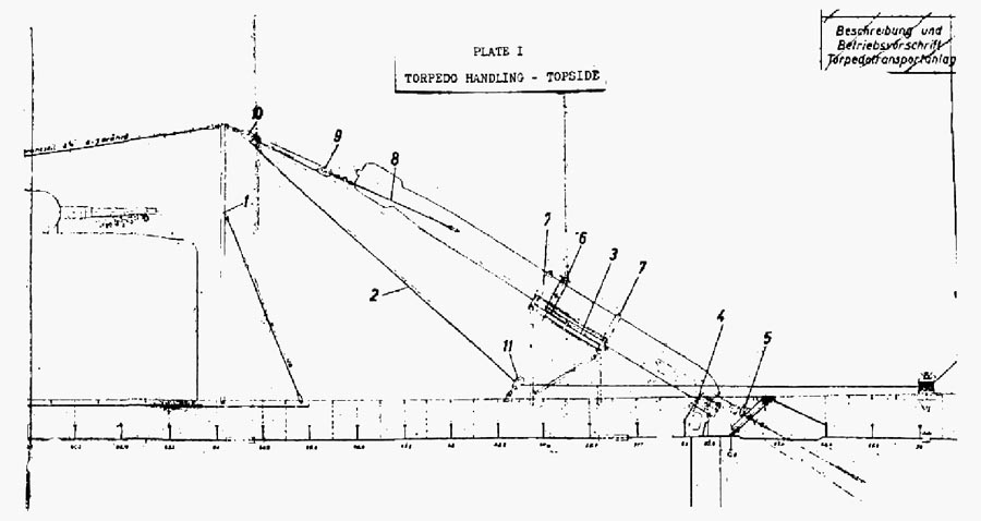
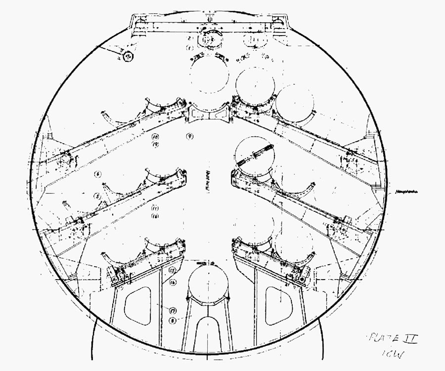
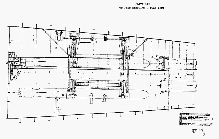
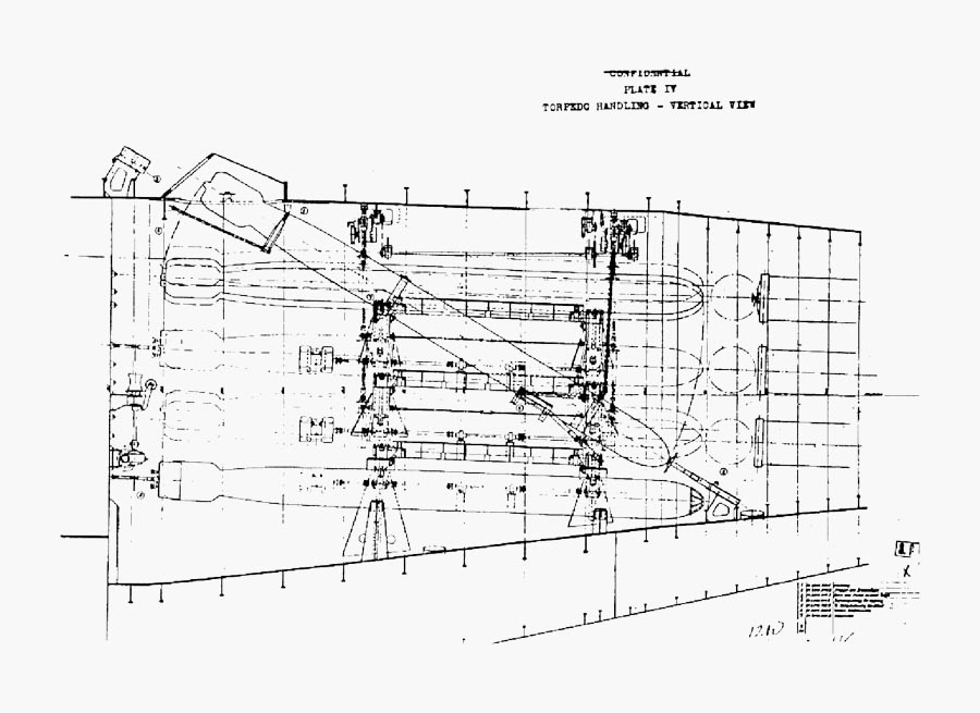
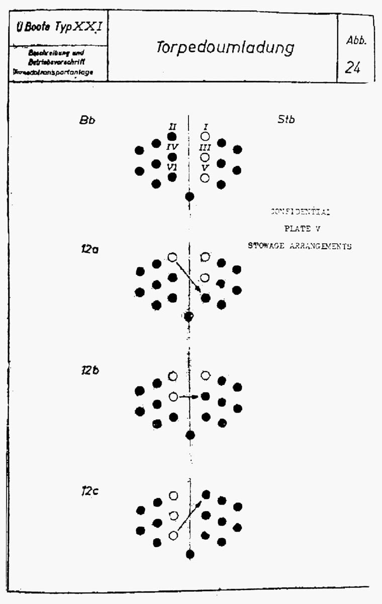
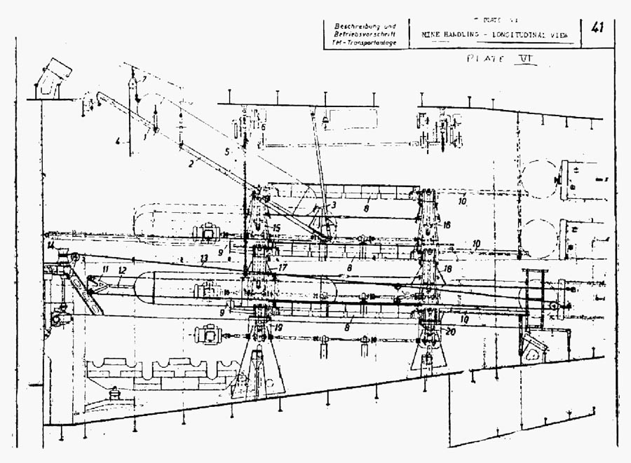
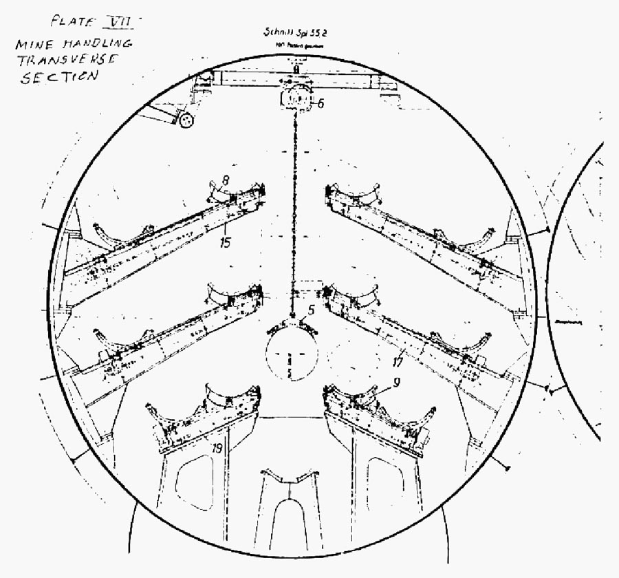
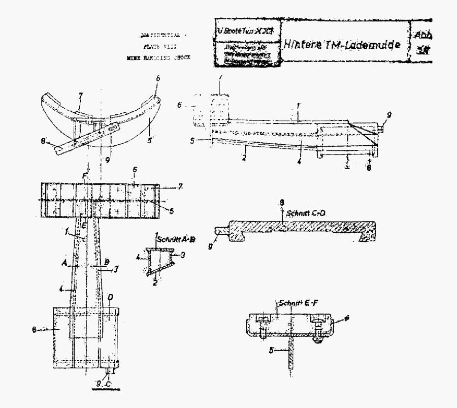
|
|||||
FORMER GERMAN SUBMARINE TYPE XXI |
|||||
MINES AND DEPTH CHARGES |
|||||
SUMMARY |
|||||
| Mine handling has been covered under the S75 report. Otherwise this section is inapplicable and the page is inserted only for record purposes. | |||||
July, 1946 |
|||||
PORTSMOUTH NAVAL SHIPYARD, PORTSMOUTH, N. H. |
|||||
- 1 - |
|||||
|
|||||
FORMER GERMAN SUBMARINE TYPE XXI |
|||||
GAS & SMOKE APPARATUS |
|||||
SUMMARY |
|||||
| No reference is made in any available material to either offensive or defensive gas warfare measures. | |||||
July, 1946 |
|||||
PORTSMOUTH NAVAL SHIPYARD, PORTSMOUTH, N. H. |
|||||
- 1 - |
|||||
|
|||||
FORMER GERMAN SUBMARINE TYPE XXI |
|||||
AMMUNITION |
|||||
SUMMARY |
|||||
| Information with respect to ammunition is limited to that obtainable from the preliminary general information book NavTechMisEu Report 312-45, and the specifications. The first lists 3450 rounds of 30MM ammunition, one part of which is to be carried as ready service ammunition. The second lists 3800 rounds of 30MM ammunition. The third does not list quantities. | |||||
| In addition to the foregoing, there would have been ammunition for the pistols listed in the general information book and specifications. | |||||
| No special ammunition handling devices were provided. | |||||
| The magazine provided fitted stowage for the ammunition boxes, with metal stanchions and battens to prevent dislodging under shock, trim or list. | |||||
July, 1946 |
|||||
PORTSMOUTH NAVAL SHIPYARD, PORTSMOUTH, N. H. |
|||||
- 1 - |
|||||
|
||||||||
FORMER GERMAN SUBMARINE TYPE XXI |
||||||||
SMALL ARMS |
||||||||
SUMMARY |
||||||||
| The general information book lists small arms as follows: | ||||||||
|
||||||||
| No mention is made in any locally available material of the amount of ammunition carried for the small arms. | ||||||||
July, 1946 |
||||||||
PORTSMOUTH NAVAL SHIPYARD, PORTSMOUTH, N. H. |
||||||||
- 1 - |
||||||||
|
|||||
FORMER GERMAN SUBMARINE TYPE XXI |
|||||
GUN BATTERIES |
|||||
SUMMARY |
|||||
| This section is not believed applicable, and is inserted merely for record. | |||||
July, 1946 |
|||||
PORTSMOUTH NAVAL SHIPYARD, PORTSMOUTH, N. H. |
|||||
- 1 - |
|||||
|
|||||
FORMER GERMAN SUBMARINE TYPE XXI |
|||||
NON-STRUCTURAL SPLINTER PROTECTION |
|||||
SUMMARY |
|||||
| No plane, rudder or propeller guards as such are provided, although the stabilizers act as propeller and stern plane guards, and the skeg as a rudder guard. | |||||
| No clearing wire is provided, and no net cutters have been considered. | |||||
July, 1946 |
|||||
PORTSMOUTH NAVAL SHIPYARD, PORTSMOUTH, N. H. |
|||||
- 1 - |
|||||
|
|||||
FORMER GERMAN SUBMARINE TYPE XXI |
|||||
BOATS |
|||||
SUMMARY |
|||||
| The hull specifications for this type of vessel provide for fitting the vessel with one 3-meter rubber boat stowed in the superstructure in a pressure-proof tank, and 30 one-man rubber boats also stowed in pressure proof containers topside. | |||||
| As boats were of a type which has been sent to the Bureau of Ships for exploitation, and are unchanged from the type provided on 9C vessels, no further comment is necessary. | |||||
July, 1946 |
|||||
PORTSMOUTH NAVAL SHIPYARD, PORTSMOUTH, N. H. |
|||||
- 1 - |
|||||
|
||||||||
FORMER GERMAN SUBMARINE TYPE XXI |
||||||||
|
||||||||
| These sections do not apply, and are inserted merely for record. | ||||||||
July, 1946 |
||||||||
PORTSMOUTH NAVAL SHIPYARD, PORTSMOUTH, N. H. |
||||||||
- 1 - |
||||||||
|
|||||
FORMER GERMAN SUBMARINE TYPE XXI |
|||||
INSTRUMENTS NOT COVERED IN OTHER GROUPS |
|||||
SUMMARY |
|||||
| This section is inapplicable and the page is inserted for record purposes only. | |||||
July, 1946 |
|||||
PORTSMOUTH NAVAL SHIPYARD, PORTSMOUTH, N. H. |
|||||
- 1 - |
|||||
|
|||||
FORMER GERMAN SUBMARINE TYPE XXI |
|||||
DAMAGE CONTROL |
|||||
SUMMARY |
|||||
| There is not the possibility of controlling damage on this type of vessel which existed in earlier types. Fewer means are available, and these are applicable, generally speaking, to a surfaced vessel if there has been any break in the pressure hull. | |||||
| List and trim control are obtained by transfer of water in the trimming system and in the regulating tank piping system, as on earlier vessels, but in certain respects these systems have in the course of simplification lost flexibility. | |||||
July, 1946 |
|||||
PORTSMOUTH NAVAL SHIPYARD, PORTSMOUTH, N. H. |
|||||
- 1 - |
|||||
|
|||||
DAMAGE CONTROL |
|||||
| GENERAL | |||||
| There is not as much choice in the means for controlling damage on this type of vessel as there is on the earlier types of vessel. The limited reserve buoyancy circumscribes the value of counter flooding, although this is possible when an exterior tank on one side has been damaged. List and trim control also fail to develop the alternatives available on earlier vessels. | |||||
| CHECK-OFF LIST | |||||
| This is similar in contents and format to that on all other types of vessel, although the listed items apply only to this type of vessel. | |||||
| PARTIES | |||||
| No information is at hand on the number of character of damage control parties. | |||||
| MEASURES | |||||
| The general information book provides tables showing the effect of damaged hull, damaged tanks, and of damaged hull and adjacent tanks on trim and weight for a surfaced vessel. For a submerged vessel the damaged tank table is indicated as applicable but it is further stated that there is no means to compensate for the flooding of a room when the vessel is submerged except for the conning tower and after compartment. | |||||
| Measures discussed are: | |||||
| a) Blowing, under which head the full capacity of the air banks is said to be sufficient to blow all MBT once at 70 meters (230 feet). Under this head is also given the possibility of blowing normal fuel oil tanks with the qualification that this is no emergency measure because of the small size of the piping. | |||||
| b) Segregation of compartments, which includes a list of valves to be closed. | |||||
- 2 - |
|||||
|
|||||
| c) Pumping, which includes curves for the surface drain pump and deep drain pump which plot the area of a leak which can be offset against the submerged depth of the vessel. | |||||
| No mention is made of counter flooding. | |||||
| Trim control is made possible by the trim tanks and their related air and water piping, which provide for the transfer of water forward or aft as desired, between the corresponding halves of the forward and after trim tanks. No transverse connection is provided, so there is no possibility of using the trim connections for list control. Additional possibilities for trim control lie in the regulating tank and regulating bunker piping, which permits transfer of water or oil either forward, aft, or across ship to the opposite half tank. The air and water piping connections between the WRT tanks and the torpedo tubes, and the further piping from the WRT tanks to the drain pump, permit control of trim and, by thwartships connections, list. It is possible to fill the tubes from the WRT tanks, or the WRT tanks by draining the tubes. It is also possible to pump the WRT tanks dry by use of either drain pump, and it is further possible to blow water from one WRT tank to the other. | |||||
- 3 - |
|||||
|
|||||
FORMER GERMAN SUBMARINE TYPE XXI |
|||||
SHOP EQUIPMENT |
|||||
SUMMARY |
|||||
| The workshop equipment provided is slightly modified from that on earlier vessels, but consists of the same units. | |||||
| The arc-welding current can be supplied from either main motor instead of the port motor only. | |||||
| Two acetylene flasks are stowed within the Conning Tower fairwater. Each has a capacity of 20-liters. | |||||
| The drill press is somewhat larger than that on earlier vessels with a 2" greater distance from head of the drill to the bench plate. | |||||
| The lathe is one of two types. Swinging clearance and bed length is the same in either type, and is substantially the same as the clearance and bed length on the lathe in 9C vessels. Features are identical. | |||||
July, 1946 |
|||||
PORTSMOUTH NAVAL SHIPYARD, PORTSMOUTH, N. H. |
|||||
- 1 - |
|||||
|
|||||
FORMER GERMAN SUBMARINE TYPE XXI |
|||||
PORTABLE TOOLS AND EQUIPMENT |
|||||
SUMMARY |
|||||
| No information has been found bearing on the number, character or type of tools which were to have been provided on board these vessels. Based on observation of practice on earlier types of vessels and the references in the available hull and machinery specifications to the general specification requirements, it is to be assumed that the intention was to provide a complete and appropriate set of tools and equipment. | |||||
July, 1946 |
|||||
PORTSMOUTH NAVAL SHIPYARD, PORTSMOUTH, N. H. |
|||||
- 1 - |
|||||
|
||||||||||||||||||||
FORMER GERMAN SUBMARINE TYPE XXI |
||||||||||||||||||||
FIRE FIGHTING |
||||||||||||||||||||
SUMMARY |
||||||||||||||||||||
| GENERAL | ||||||||||||||||||||
| Fire fighting equipment on this type of vessel has been increased to 8 CO2 extinguishers, distributed as follows: | ||||||||||||||||||||
|
||||||||||||||||||||
| They are the same 6 kg (13.3 lb.) units used on earlier types of vessel. The deck wash line is retained for possible value on a fire topside. | ||||||||||||||||||||
| Fire fighting instructions remain unchanged from those on 9C vessel. | ||||||||||||||||||||
| COMMENT | ||||||||||||||||||||
| While the number of extinguishers has been increased, the size of the vessel has also been increased. While the number of extinguishers in the maneuvering and engine rooms now correspond to those which would have been provided under U.S. normal practice, three rooms are left without immediate means for fighting fire. | ||||||||||||||||||||
July, 1946 |
||||||||||||||||||||
PORTSMOUTH NAVAL SHIPYARD, PORTSMOUTH, N. H. |
||||||||||||||||||||
|
||||||||||||||||||||
FORMER GERMAN SUBMARINE TYPE XXI |
||||||||||||||||||||
SALVAGE |
||||||||||||||||||||
SUMMARY |
||||||||||||||||||||
| The general information book specifies the following salvage equipment to be carried on board: | ||||||||||||||||||||
|
||||||||||||||||||||
| There is no way of checking the foregoing, as the equipment on board when the vessels arrived in the United States did not correspond to the specified equipment. Among other differences, there were many inflatable life jackets on board, although none are listed in the general information book. | ||||||||||||||||||||
| The type of equipment found aboard does not depart from that found on the X-B vessel. | ||||||||||||||||||||
July, 1946 |
||||||||||||||||||||
PORTSMOUTH NAVAL SHIPYARD, PORTSMOUTH, N. H. |
||||||||||||||||||||
BIBLIOGRAPHY |
||
| The bibliography has been prepared in two divisions, one for listing alphabetically available German reference publications and plans and U.S.N. reference reports, and one for associating appropriate S group numbers (from Navy Filing Manual) with the references listed in the first part. The numbers shown opposite that of the S group corresponds to the number assigned a reference in the first part of the bibliography. | ||
- 1 - |
||
| 1. List of German References | ||||||||||||||||||||||||||||||||||||||||||||||||||||||||||||||
| a. German publications of general nature. | ||||||||||||||||||||||||||||||||||||||||||||||||||||||||||||||
|
||||||||||||||||||||||||||||||||||||||||||||||||||||||||||||||
- 2 - |
||||||||||||||||||||||||||||||||||||||||||||||||||||||||||||||
|
||||||||||||||||||||||||||||||||||||||||||||||||||||||||||
- 3 - |
||||||||||||||||||||||||||||||||||||||||||||||||||||||||||
|
||||||||||||||||||||||||||||||||||||||||||
- 4 - |
||||||||||||||||||||||||||||||||||||||||||
| b. U.S.N. Reports. | ||||||||||||||||||||||||||||||||||||||||||||||||||
|
||||||||||||||||||||||||||||||||||||||||||||||||||
- 5 - |
||||||||||||||||||||||||||||||||||||||||||||||||||
|
||||||||||||||||||||||||||||||||||||||||||||||||||||||
- 6 - |
||||||||||||||||||||||||||||||||||||||||||||||||||||||
|
||||||||||||||||||||||||||||||||||||||||||||||||||||||||||||||
- 7 - |
||||||||||||||||||||||||||||||||||||||||||||||||||||||||||||||
|
||||||||||||||||||||||||||||||||||||||||||||||||||||||||||
- 8 - |
||||||||||||||||||||||||||||||||||||||||||||||||||||||||||
|
||||||||||||||||||||||||||||||
- 9 - |
||||||||||||||||||||||||||||||
| c. German publications applicable to type. | |||||||||||||||||||||||||||||||||||||||||||||||||||||||||||||||||||||||||||||||||||||
|
|||||||||||||||||||||||||||||||||||||||||||||||||||||||||||||||||||||||||||||||||||||
- 10 - |
|||||||||||||||||||||||||||||||||||||||||||||||||||||||||||||||||||||||||||||||||||||
| c. German publications applicable to type. | ||||||||||||||||||||||||||||||||||||||||||||||||||||||||||||||||||||||||||
|
||||||||||||||||||||||||||||||||||||||||||||||||||||||||||||||||||||||||||
- 11 - |
||||||||||||||||||||||||||||||||||||||||||||||||||||||||||||||||||||||||||
| d. German plans applicable to type. | ||||||||||||||||||||||||||||||||||||||||||||||||||||||||||||||||||||||||
|
||||||||||||||||||||||||||||||||||||||||||||||||||||||||||||||||||||||||
- 12 - |
||||||||||||||||||||||||||||||||||||||||||||||||||||||||||||||||||||||||
|
||||||||||||||||||||||||||||||||||||||||||||||||||||
- 13 - |
||||||||||||||||||||||||||||||||||||||||||||||||||||
XXI |
||||||||||||||||||||||||||||||||||||||||||||||||||||||||||||||||||||||||||||||
BIBLIOGRAPHY - PART 2 |
||||||||||||||||||||||||||||||||||||||||||||||||||||||||||||||||||||||||||||||
|
||||||||||||||||||||||||||||||||||||||||||||||||||||||||||||||||||||||||||||||
- 1 - |
||||||||||||||||||||||||||||||||||||||||||||||||||||||||||||||||||||||||||||||
|
||||||||||||||||||||||||||||||||||||||||||||||||||||||||||||||||||||||||||||||||||||||||||||||||||||||
- 2 - |
||||||||||||||||||||||||||||||||||||||||||||||||||||||||||||||||||||||||||||||||||||||||||||||||||||||
|
||||||||||||||
- 3 - |
||||||||||||||