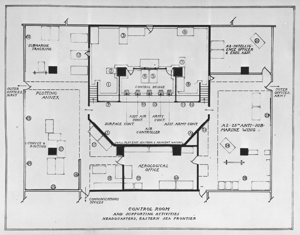
Joint Operations Office, Control Room and Plotting Annex
| The focus of the Joint Operations Control Room was the Control Bridge: The station of the three controllers, - Navy Air, Army Air, and Surface. Supporting activities were assigned areas according to their functional relationship to the bridge. Thus the controllers, stationed at an elevation of five feet, were faced with an approximately 19' high x 28' long master chart (Main Situation Board) on which ship and aircraft movements were continually plotted by means of symbols. The plotters were stationed at a long counter-like log-desk below. The Caribbean area was portrayed in linoleum on the floor of the lower control room area, the Master Chart thus being visually related to the southern waters adjacent. The Air Controllers were stationed at immediately adjacent posts, flanked on their other sides by their assistants. The Surface Controller was stationed at the end nearest to the Plotting Annex, the Ship Plotter below. As may be seen on the plan, the Air Operational Information and A-2 desks were immediately behind the Controllers, with communication and recording functions stemming out from the Control Bridge proper. The photographs illustrate activities of the diverse elements which contributed to the joint operations of the Control function. |
| LEGEND |
|
CONTROL ROOM, RAISED
DECK |
|
| 1. Observation Deck, enclosed | 5. A-2 (Intelligence), Army |
| 2. Communications Desk, Navy | 6. Controllers' Chart Table |
| 3. Recorder, Navy | 7. A-3, Journal Desk, Army |
| 4. Air (Combat) Operational Information, Navy | 8. Eastern Defense Command, Liaison, Enclosed |
CONTROL ROOM, BELOW |
|
| 9. Ship Plot Watch Officer | S. Surface Craft Mission Board |
| 10. Air Plot, Navy | A. Aircraft Availability and Missions Boards, Army and Navy |
| 11. Air Plot, Army | |
PLOTTING ANNEX |
|
| 12. Submarine-tracking plot | 15. World Chart |
| 13. Merchant Marine Plot, ESF | 16. Observation Craft Plot, ESF |
| 14. Merchant Marine Plot, Caribbean | 17. Ship Plot, Desks and Drafting Tables |
| 18. Chart Section and Files | |
AEROLOGICAL OFFICE |
|
| 19. Teletype, etc. | 20. Drafting Tables, Aerological Officer |
A-2 ARMY INTELLIGENCE |
|
| 21 Intelligence Officer, 25th Anti-Submarine Wing | 23. World Map |
| 22. Strategic Intelligence, Maps | 24. Strategic Officers |
| 25. Drafting and Files | |
| GENERAL VIEW OF THE CONTROL ROOM This photograph shows the Control Bridge overlooking the Main Situation Board (Master Plot) and Air Plot Watch Officers in the "dugout" below. |
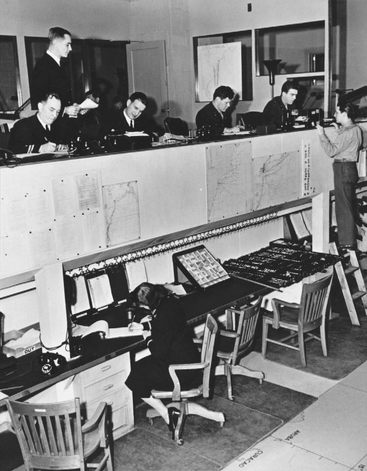
| CONTROL BRIDGE AND AIR PLOT Another view of Air Controlers and assistants on the bridge. View of Air Plot stationed below, shows work table, command phones, log, resevoir of aircraft symbols, patrol charts, etc. Air Plot maintained a log of aircraft movements, plotted them on the Main Situation Board, assembled and posted aircraft availability data, and posted synopses of current operations on the Missions Boards. |
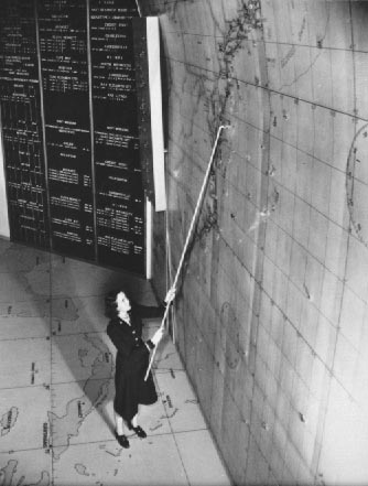
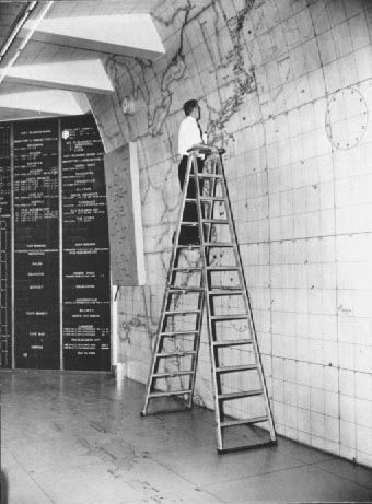
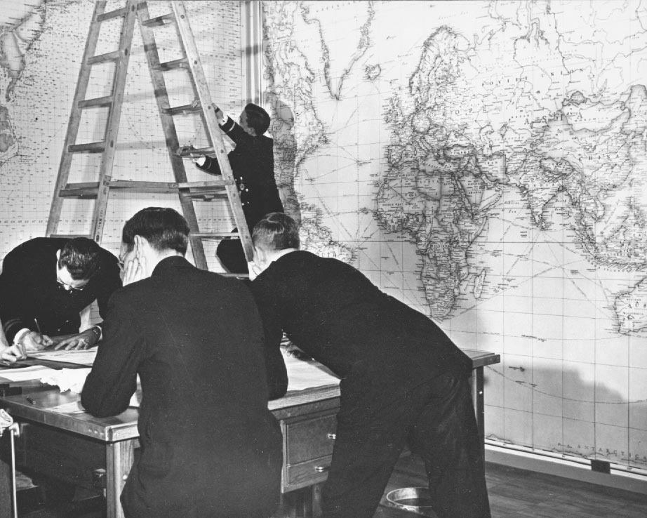
| Method of moving symbols that were beyond arms' reach |
| Moving symbols on the Master Plot |
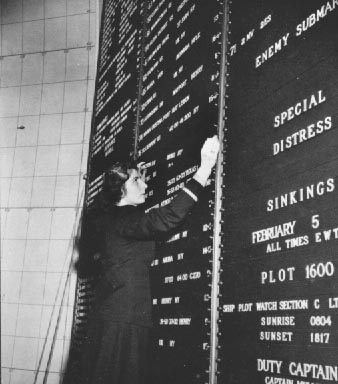
| Close-up showing method of inserting strips on Mission Board |
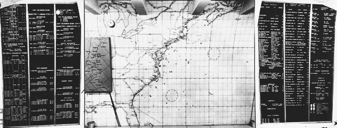
| MASTER PLOT AND WING MISSION BOARDS (Note: For security purposes the pictures of the plot and mission boards were not taken on the same day) |
| VIEW OF CONTROL BRIDGE FROM EASTERN DEFENSE COMMAND LIAISON OFFICER'S DESK The Liaison Officer, Eastern Defense Command, collected and exchanged information of operational significance or mutual interest with all offices concerned, especially the Operational Information and Coastal Information Watch Officers, . |
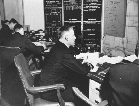
| AIR CONTROLLER, NAVY The primary duty of the Air Controller was to see that prompt and vigorous action was taken upon all enemy contact reports, aircraft or surface distress situations, and other occasions for action by the Frontier Air Forces. He acted for the Air Officer, Eastern Sea Frontier. Controller watches were maintained continually as were all supporting functions. |
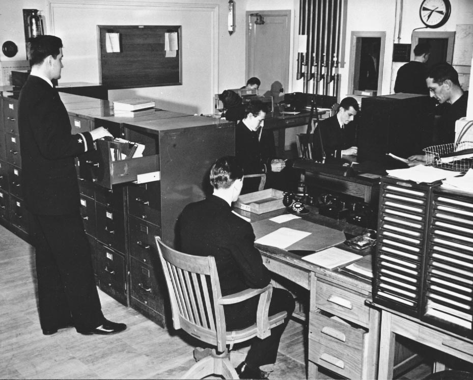
| GENERAL VIEW : COMMUNICATIONS OFFICE This photograph shows a portion of the Communications Office. The teletype room and Code Board room are not illustrated. The pneumatic tubes whereby dispatches were transmitted to the Communications Deck at the back of Control Bridge (See plan) may be seen next to the door in the background. |
|
Communications Officer on Control Bridge sending dispatch by pneumatic tube |
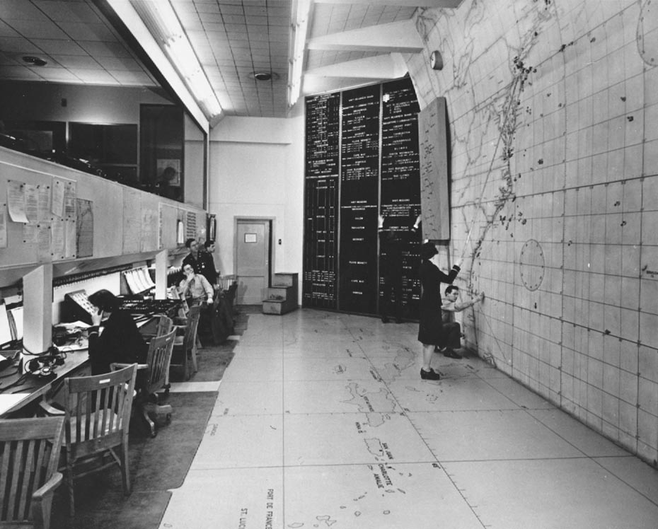
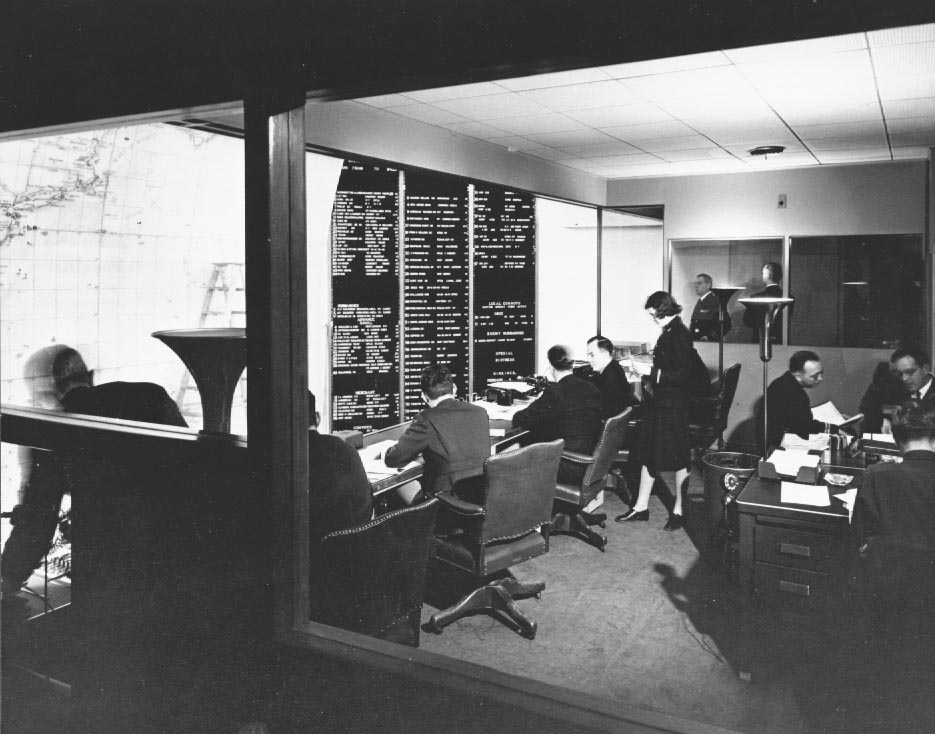
| ENEMY SUBMARINE TRACKING SECTION The photograph shows the Enemy Submarine Tracking Section. Its duty, in general, was to evaluate all available information on ememy submarines with the purpose of predicting movements and capabilities of the enemy. The assimilated data was graphically presented on the wall plot, which may be viewed from a window in the wall of the Control Bridge (See plan). |
| ENEMY SUBMARINE PLOT The photograph shows the wallchart used for plotting. This chart, measuring approximately 12' high X 13' long, was backed by steel to enable movable magnitized symbols to adhere. This method was used on all the wall-plots described below. |
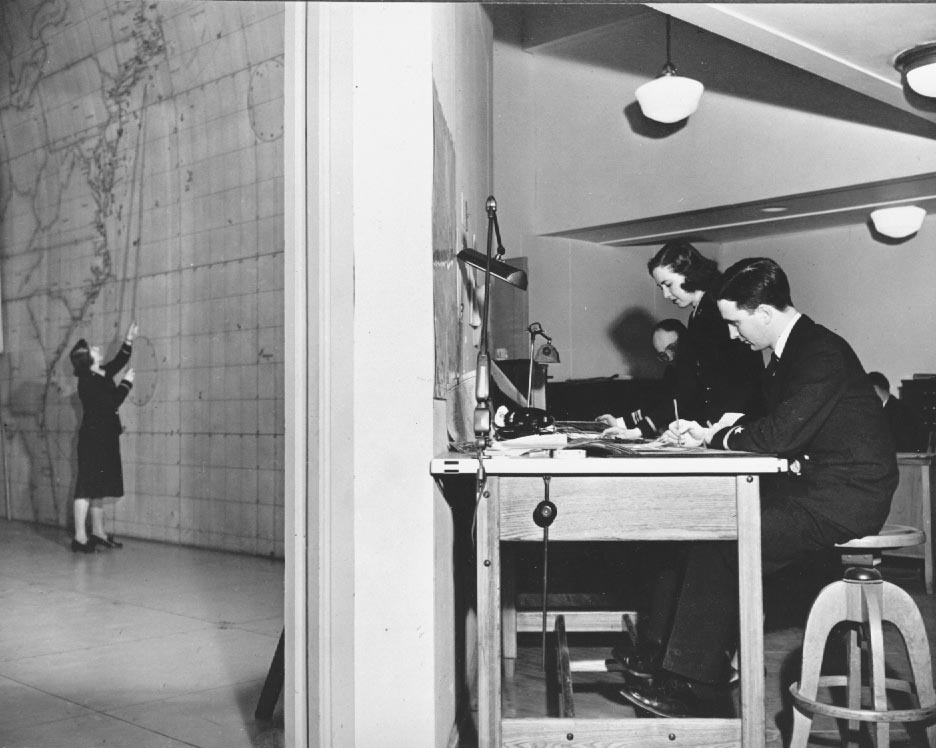
| MERCHANT MARINE SECTION, SHIP PLOT The photograph gives a general view of the Merchant Marine Section (Convoy and Routing). The primary duty was to maintain accurate plots of the movements of all surface craft and all friendly submarines within the Eastern Sea Frontier and adjacent waters. This data contributed to the posting of specific information on the Main Situation Board (Master Plot) in the Control Room. |
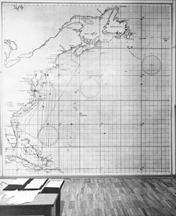
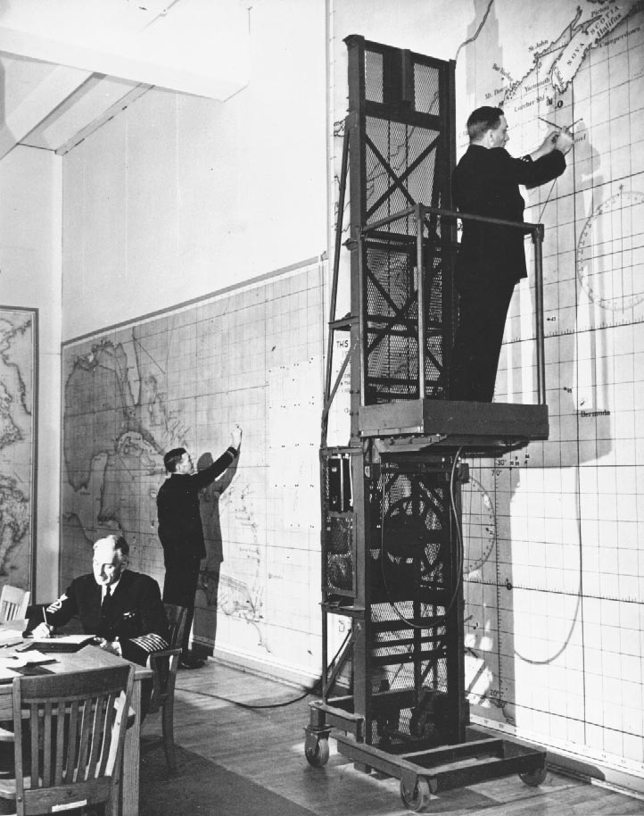
| MERCHANT MARINE PLOT The photograph shows the wall-plot of the Eastern Sea Frontier, measuring approximately 18' long X 17' high. An adjacent plot of the Caribbean waters (10' - 6" X 19') appears in the proceeding photograph. The coastal shipping lanes were indicated by movable colored stripes. |
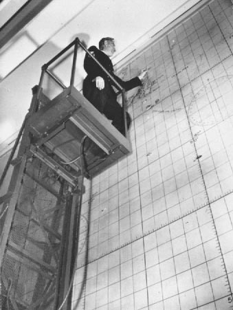
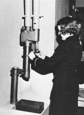
| View of movable elevator to facilitate plotting |
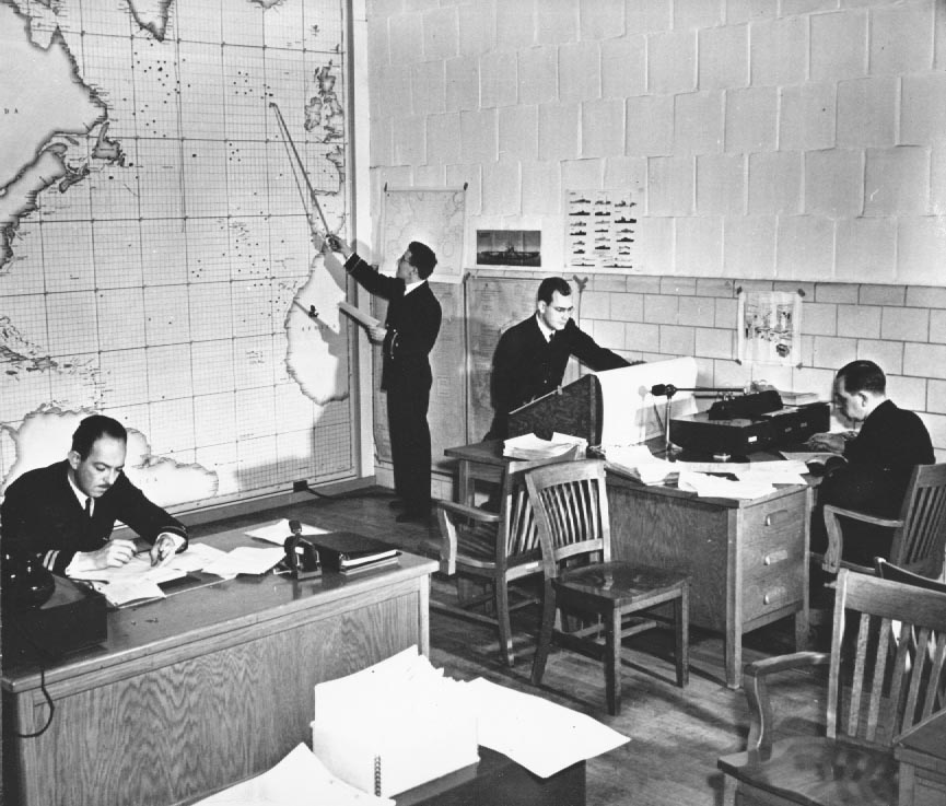
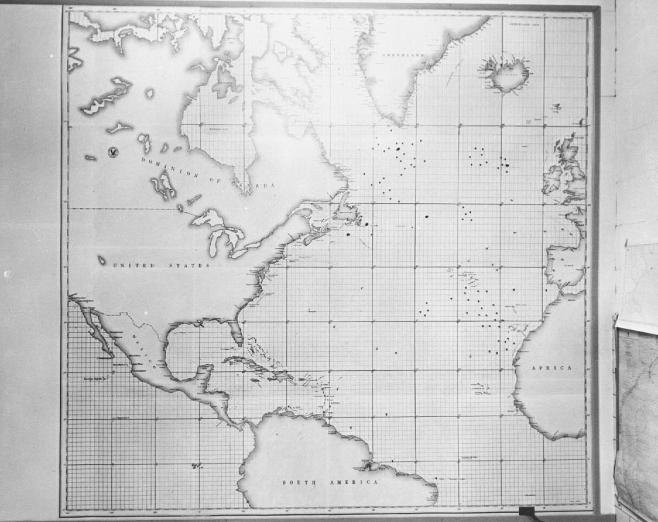
| GENERAL VIEW, WORLD MAP AND OBSERVATION PLOT This photograph shows Ships Plot Watch Officers working on charts at drafting tables. In the background to the left is the plot of the coastal observation craft (approx. 12' - 6" X 19') on which the hostilities in all theatres were reflected |
| MAIN SITUATION BOARD, CONTROL ROOM AND CORNER OF PLOTTING ANNEX This photograph taken at the doorway leading from Plotting Annex to the Control Room, shows (right) Ship Plot Officers at work at drafting tables, and (left) a glimpse of the Control Room with an officer moving a symbol on the Main Situation Board (Master Plot). |
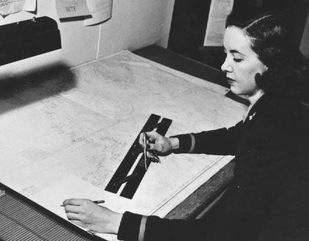
| Close-up of chart work, Ship Plot |

| GENERAL VIEW: AEROLOGICAL OFFICE The section illustrated here kept the weather board corrected to latest teletype sequences; assembled weather data, helped prepare weather maps, relayed reports from Weather Bureau (La Guardia Field), and supplied weather information and forcasts as required. |

| WEATHER BOARD This board faced the Control Bridge and indicated, by means of colored lights, the current flying conditions at the various air fields and stations. Green indicated contact, amber - instrument, and red - closed. |
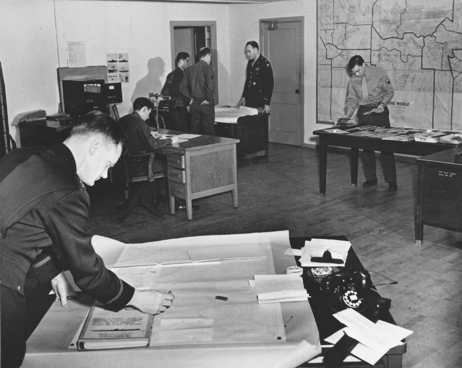
| GENERAL VIEW: A-2 OFFICE 25TH ANTI-SUBMARINE WING The photograph illustrates the offices of A-2; the intelligence headquarters of the control centers of Army Anti-Submarine Warfare within the Frontier. This room was used for plotting, strategic, and adminsitrative purposes. The office of the ranking officer (21 on the plan) lies through the open door. |