F-Tafel
Table for Simplified Calculation of Position Lines by Altitude
Translation by Jerry Mason
2154 |
||
| F-Table | ||
III. Edition |
||
 |
||
 |
Click the flag to view the above page from the original German |
2154 |
||
| F-Table | ||
Table for simplified calculation of |
||
of position lines by altitude |
||
3rd Edition |
||
On behalf of the Supreme Command of the Navy
|
||
| issued by the German Naval Observatory | ||
|
||
Hamburg 1941 |
||
|
|
| II | ||||||||||||||||||||||||||||||||||||||
Forward to the 3rd Edition |
||||||||||||||||||||||||||||||||||||||
|
||||||||||||||||||||||||||||||||||||||
|
|
III |
||||||||||||||||||||||||||||||||||||||||||||||||||||||||||||||||||||||||||||||
Contents |
||||||||||||||||||||||||||||||||||||||||||||||||||||||||||||||||||||||||||||||
|
||||||||||||||||||||||||||||||||||||||||||||||||||||||||||||||||||||||||||||||
|
||||||||||||||||||||||||||||||||||||||||||||||||||||||||||||||||||||||||||||||
|
|
V |
||
Introduction and Usage Instructions |
||
for the F-Table |
||
| A. Overview of position line calculation using the F-Table | ||
| 1. Construction of the F-Table | ||
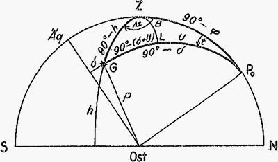
| The altitude and azimuth of a star can be calculated quickly and reliably using the F-Table. By breaking down the nautical astronomical triangle Zenith-Pole-Star into two right spherical triangles (See Figure 1) a formula system is derived whose two auxiliary variables (U and V) give log sin h by the shortest route, in fact according to the formula: | ||
log sin h = V + log sin (δ + U), |
||
where by tan U = cos t · cotan φ |
||
sin B = sin t · cos φ |
||
| V = log cos B. | ||
| Therefore the F-Table is so constructed that with the known values: | ||
declination of the star (δ), |
||
assumed latitude (φa)*), |
||
assumed hour angle (ta)**) |
||
| as input, these auxiliary values are extracted. | ||
| With two further auxiliary variables P and Grenz-δ (Gr.δ) taken simultaneously give the azimuth according to the formula: | ||
| sin Az = cos P · sec h, whereby | ||
| cos P = sin t · cos δ. | ||
| Gr. δ is used for determining the azimuth quadrant in those cases where it is not clear if the upper or lower pole applies. | ||
| ___________ | ||
| *) With φa designated as the full latitude, which lies closest to the dead reckoning latitude. | ||
| **) With ta designated as the hour angle closest to the calculated hour angle and rounded to full minutes whose number of minutes is divisible by 4. | ||
|
|
| VI | ||||||||||||||||||
| 2. Brief Summary of the usage rules for the calculation of position lines by altitude with the F-table | ||||||||||||||||||
| 1. Enter the dead reckoning position (φg, λg), the φg at the nearest full degree of latitude φa and the observed altitude ✳. | ||||||||||||||||||
| 2. Enter the hour angle calculated in the usual way, rounded to the nearest value divisible by 4m and the δ. | ||||||||||||||||||
| 3. Calculate hb from observed (✳) and total correction (Gb.). | ||||||||||||||||||
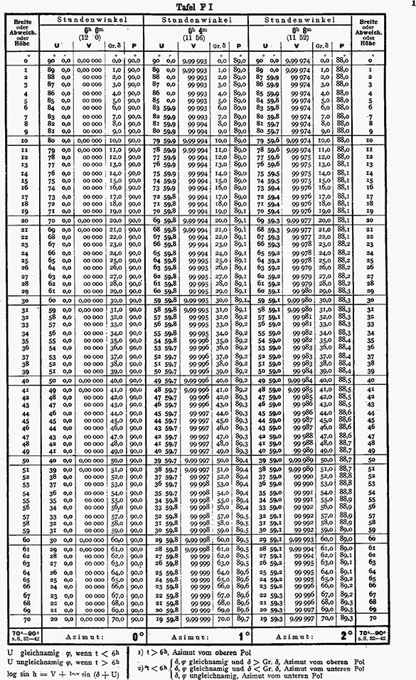
| 4. Extract P with ta and δ from Table F I (or Table F XI). | ||||||||||||||||||
| 5. Extract U, V, and Gr. δ with ta and φa from Table F I. | ||||||||||||||||||
| 6. Determine the quadrant of the azimuth. | ||||||||||||||||||
| Rule: If te, then azimuth is east. | ||||||||||||||||||
| If tw, then azimuth is west. | ||||||||||||||||||
| If t > 6h, then azimuth is from the upper pole. | ||||||||||||||||||
|
||||||||||||||||||
| 7. Designate U. | ||||||||||||||||||
| Rule: If t < 6h, then U same as φ. | ||||||||||||||||||
| If t > 6h, then U opposite φ. | ||||||||||||||||||
| Generate δ + U (add algebraically). | ||||||||||||||||||
| 8. Take the log sin from the value calculated after step 7 from table F II and add to V. | ||||||||||||||||||
| 9. With this sum take the altitude h from table F II. | ||||||||||||||||||
| 10. With h and P take azimuth from Table F I. If the sought after P-value is located here bellow the dotted line, use Table F XI for more accurate azimuth determination. | ||||||||||||||||||
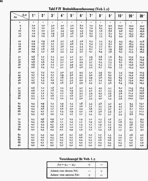
| 11. Take the hour angle correction (correction for t) from table F III with φa, Az and the seconds neglected in the rounding of the hour angle (Δt). | ||||||||||||||||||
| Rule: Correction for t = + if calculated with too great an assumed t, | ||||||||||||||||||
| Correction for t = – if calculated with too small an assumed t. | ||||||||||||||||||
| 12. Plotting position lines | ||||||||||||||||||
| a) Without baseline shift: | ||||||||||||||||||
| The starting point for the plotting of all observations is φa and λg (Examples 1 and 2). | ||||||||||||||||||
| b) With baseline shift: | ||||||||||||||||||
| either | ||||||||||||||||||
| for all observations apply to the Oa [assumed position] of the last observation the corrected latitude difference and signs of the positions established this way | ||||||||||||||||||
| or | ||||||||||||||||||
| take the latitude corrections (Correction for φ) from Table F IV with Az and φa-φg and apply them to the calculated altitudes, then plot all observations from the dead reckoning position for the last observation made (See Examples 3b and 4b). | ||||||||||||||||||
|
|
VII |
||||||||||||||||
B. Explanatory notes to the F-Table |
||||||||||||||||
| 1. Calculation of hr | ||||||||||||||||
 |
||||||||||||||||
Figure 1 The Nautical-Astronomical Triangle |
||||||||||||||||
| Figure 1 definitions: | ||||||||||||||||
| Z = zenith of the observer | ||||||||||||||||
| Po = upper pole | ||||||||||||||||
| G = star. | ||||||||||||||||
| In the figures that follow values are specified with the commonly used abbreviations: | ||||||||||||||||
| ZPo = 90° – φ | ||||||||||||||||
| PoG = 90° – δ, if δ is the same sign as φ | ||||||||||||||||
| (PoG = 90° + δ, if δ is the opposite sign of φ) | ||||||||||||||||
| XG = 90° – h | ||||||||||||||||
| ZL = B = plumb line from Z to the hour circle of the star (auxiliary value) | ||||||||||||||||
| ZPoG = t = hour angle of the star (te or tw) | ||||||||||||||||
| PoL = U (auxiliary value) | ||||||||||||||||
| GL = 90° – (δ + U), bearing in mind whether δ is north or south. | ||||||||||||||||
| By applying Napier's rule to the two right triangles and ZLPo and ZLG one obtains: | ||||||||||||||||
|
||||||||||||||||
| U is the same sign as φ for t < 6h and opposite for t > 6h. | ||||||||||||||||
| Table F I (pages 1-42) gives: | ||||||||||||||||
U and V (V = log cos B) |
||||||||||||||||
| with the inputs: | ||||||||||||||||
| t from 4m to 4m | ||||||||||||||||
| φ from degree to degree. | ||||||||||||||||
| One sets log cos B = V, so the calculation of altitude proceeds | ||||||||||||||||
| log sin h = log cos B + log sin (δ + U) becomes | ||||||||||||||||
| log sin h = V + log sin (δ + U). | ||||||||||||||||
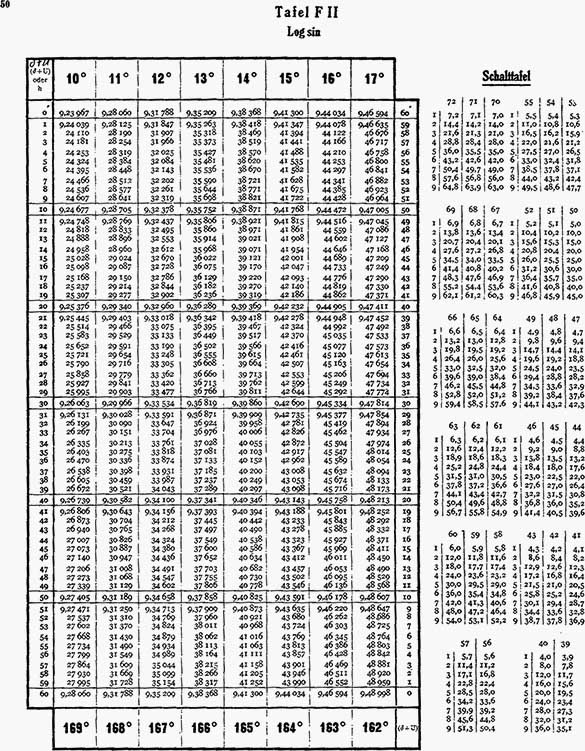
| The log sin can be found in Table F II (Pages 43-58). | ||||||||||||||||
| For the extraction of U and V the rounded to full degree of latitude φa and the rounded hour angle ta whose number is divisible by 4 minutes or is equal to 0m is used. The amounts neglected by the assumed values shall be taken into account by affixing the correction for hour angle or correction for latitude. Since azimuth is required for both corrections, the explanation of the determination of the azimuth takes place first. | ||||||||||||||||
|
|
| VIII | ||||||||||||||||||||||||||||||
| 2. Determination of Azimuth | ||||||||||||||||||||||||||||||
| Calculation of the azimuth is done with the time-altitude-azimuth formula: | ||||||||||||||||||||||||||||||
sin Az = sin t cos δ sec h. |
||||||||||||||||||||||||||||||
| For this purpose one: | ||||||||||||||||||||||||||||||
sin t cos δ = cos P, |
||||||||||||||||||||||||||||||
| then sin Az = cos P sec h. | ||||||||||||||||||||||||||||||
| The auxiliary variable P is the spherical distance of the star from the east or west point. It is given in Table F I to an accuracy of 0.1°, in Table F XI to 1' and is taken with the inputs of ta and δ. The taking of the azimuth in Table F I with h and P as input may in some cases be uncertain (Az ∼ 90° or at high altitudes). This occurs when there are variations when going through the azimuth adjacent P-values in a horizontal line of less than 0.3°. This is denoted in table F I by a dotted line. If the searched for P value is below this line, the entire azimuth determination is repeated with table F XI, in other words, P can be found there with input of ta and δ and the azimuth with h and P. For altitudes > 70° always use Table XI. | ||||||||||||||||||||||||||||||
| If the azimuth is close to 90°, which is the case when P and h are approximately equal, so interpolation for h can be performed easily, as the change in h is equal to the change in P. | ||||||||||||||||||||||||||||||
| Example: | ||||||||||||||||||||||||||||||
| With ta = 4h 48m and δ = 23°26.5'N results in P = 29°15' and h = 24°14', therefore the azimuth must lie near 90°. A look at the P-values near Az 90° shows the difference between two consecutive P-values is very nearly equal to 1°. In the given example the following values for P can be found in table F XI (Page 84): | ||||||||||||||||||||||||||||||
|
||||||||||||||||||||||||||||||
| For a 14' increase in h there is also a 14' increase in P. | ||||||||||||||||||||||||||||||
| One can therefore bring the amount exceeding the full degree number (in arc minutes) with h and P deducted and then enter Table F XI with these two values. Therefore in the example above for h = 29°0' the value of P = 29°15' – 0°14' = 29°1'. Its corresponding value is read from the 89° azimuth column. | ||||||||||||||||||||||||||||||
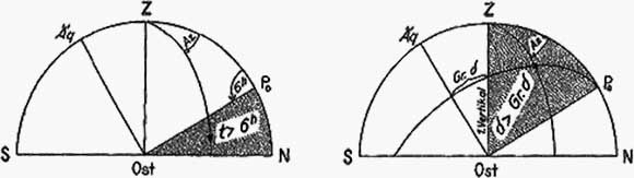
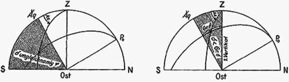
| Determining the quadrant (Figures 3-6) | ||||||||||||||||||||||||||||||
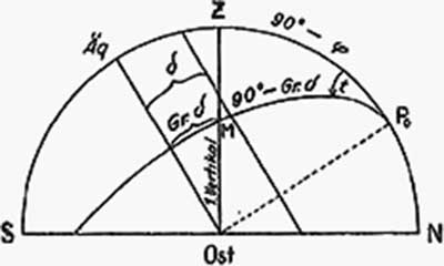
| The F-Table only provides azimuth to 90°,Therefore the quadrant of the azimuth must still be determined; if t > 6h, the azimuth counts from the upper pole, if δ is opposite to φ, from the lower pole (Figures 3 and 4). For the case t < 6h and δ the same as φ, the quadrant is doubtful an auxiliary value Gr.δ is introduced for deciding. Gr. δ is the difference of the intersection M of the hour circle of the star with the prime vertical circle at the moment of observation (See Figure 2). | ||||||||||||||||||||||||||||||
|
|
IX |
||||||||||||||
 |
||||||||||||||
Figure 2 The depiction of limit δ |
||||||||||||||
| From the triangle MZPo it follows that Gr. δ is a function of φ and t, and by Napier's rule: | ||||||||||||||
tan Gr. δ = tan φ cos t. |
||||||||||||||
| One finds Gr. δ in Table F I with the inputs of ta and φa in the same row as the values U and V*). | ||||||||||||||
| The following rules apply to determine the quadrant of the azimuth: | ||||||||||||||
|
||||||||||||||
Azimuth from the upper pole |
||||||||||||||
| Figure 3 t < 6h Figure 5 δ same as φ and δ > Gr. δ | ||||||||||||||
 |
||||||||||||||
Azimuth from the lower pole |
||||||||||||||
| Figure 4 δ opposite to φ Figure 6 δ same as φ and δ < Gr. δ | ||||||||||||||
 |
||||||||||||||
| The azimuth counts to the east (west) when the hour angle is east (west). | ||||||||||||||
| Gr. δ is only needed when t < 6h and δ is the same as φ. | ||||||||||||||
| When t = 6h, azimuth is counted from the upper pole, | ||||||||||||||
| when δ = Gr. δ, the azimuth is the same as 90°. | ||||||||||||||
| ___________ | ||||||||||||||
| *) By comparing the formulas for Gr. δ and U (See under B 1) one can see that Gr. δ is also obtained to an accuracy of 0.1' if one entered the U column with 90° – φ instead of φ. | ||||||||||||||
|
|
| X | |||
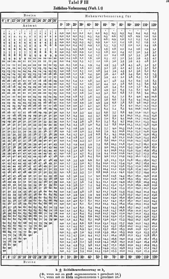
| 3. Hour angle correction (Correction for t) (Table F III, Page 59-63) | |||
| This is calculated by the formula: | |||
Correction for t = sin Az cos φ Δt*). |
|||
| After the as yet uncorrected azimuth is determined by section 2, from Table F III with latitude φa and this azimuth as an input as well as the hour angle difference: | |||
Δt = ta – tr (tr = calculated hour angle) |
|||
| hour angle correction is taken in arc minutes. Since the table is given values of 10s to 10s, intermediate values are interpolated. | |||
| Hour angle correction is + if calculated with too great a ta. | |||
| Hour angle correction is – if calculated with too small a ta. | |||
C. Worked examples and analysis of observations |
|||
by plotting |
|||
| The following are some examples of the use of the F-Table taken from nautical practice. The calculations use a form based on the exercise book: "Position lines with F-table". | |||
| 1. Position line without baseline shift | |||
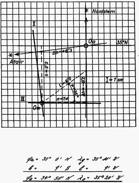
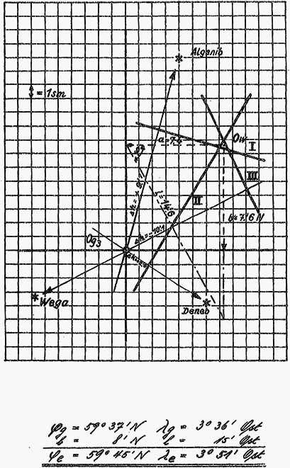
| The calculated altitude is only adjusted for the assumed hour angle by applying the hour angle correction. So Δt = hb – hr applies strictly to the intersection of Oa of the assumed full latitude φa and estimated Longitude λg, therefore this is the starting point of the plot. In Examples 1 and 2, Page XII-XV, the calculation, construction of two position lines and the determination of the true ship's position Ow are reproduced. The difference in longitude, is also easily determined graphically according to the formula l [longitude] = a [horizontal distance] · sec φ [assumed φ]. | |||
| 2. Position line with baseline shift | |||
| When two observations are not made at the same location, one must displace the position line from the first observation corresponding to the shift in position in the meantime. The intersection point of the displaced first position line with the position line determined at the second observation is the ship's position at the time of the second observation. | |||
| a) Solution by plotting only. | |||
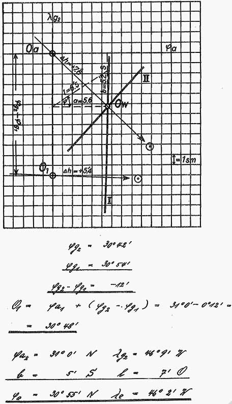
| For this purpose, one takes course and distance from an arbitrary point on position line I and through the end point, run a line parallel to position line I. Then, one draws from Og2 the calculated for this location position line II. As Og2 any point on the shifted position line may be I used for the calculation. The intersection of position line II with the shifted position line I is Ow at the time of the second observation. This solution should be used when it is plotted on the sea chart (Sumnerkarte) or on graph paper. | |||
| Example: | |||
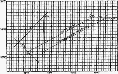 |
|||
This interpretation is based on the observations of Example 3, see Pages XVI and XVII |
|||
| ___________ | |||
| *) Δt is given in minutes, so the correction for t in arc-minutes is given by the formula | |||
Correction for t = 15 sin Az cos φ Δt. |
|||
|
|
XI |
|||||||||||||||||||||||||||||||||||||||||||||||||||||||||||||||||||||||
|
|||||||||||||||||||||||||||||||||||||||||||||||||||||||||||||||||||||||
|
|
| XII | ||
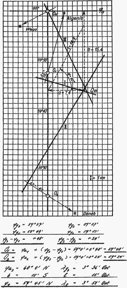
Example 1: 2 Star observations without baseline shift |
||
 |
||
|
|
XIII |
||
Illustration of Example 1 |
||
 |
||
|
|
| XIV | ||
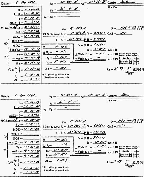
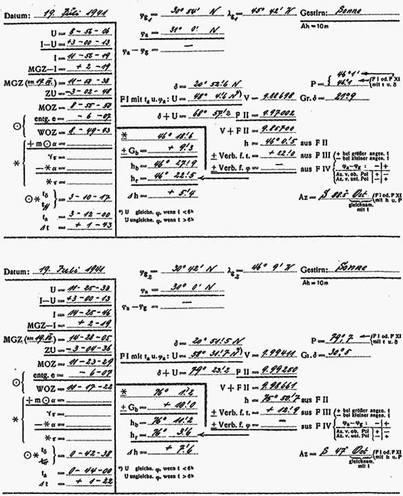
Example 2: 2 Star observations without baseline shift |
||
 |
||
|
|
XV |
||
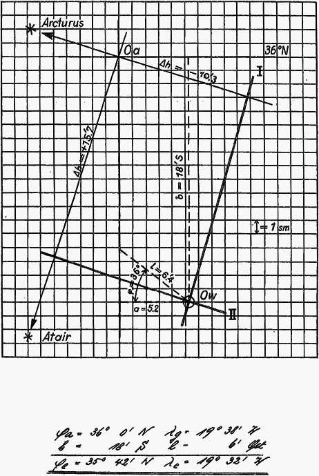
Illustration of Example 2 |
||
 |
||
|
|
| XVI | ||
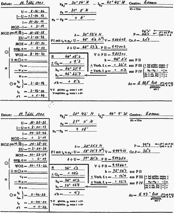
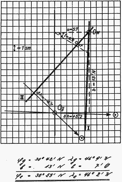
Example 3a: 2 Sun observations with baseline shift |
||
without Latitude correction |
||
 |
||
|
|
XVII |
||
Illustration of Example 3a |
||
 |
||
|
|
| XVIII | ||
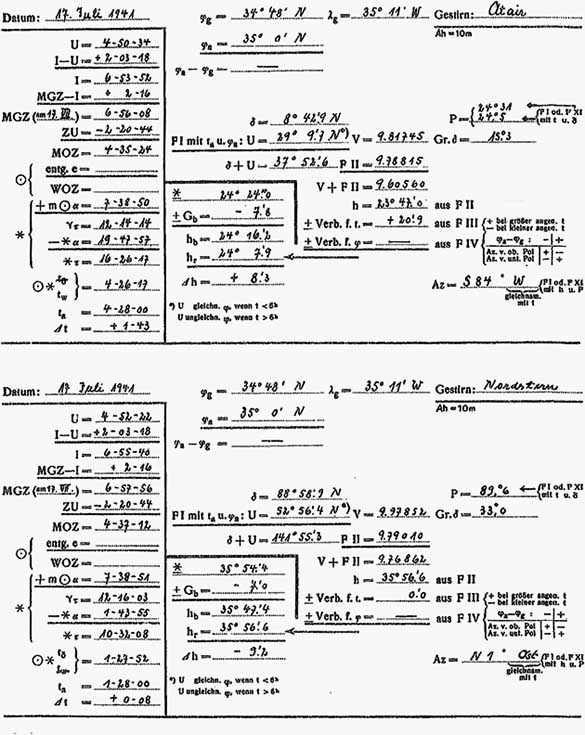
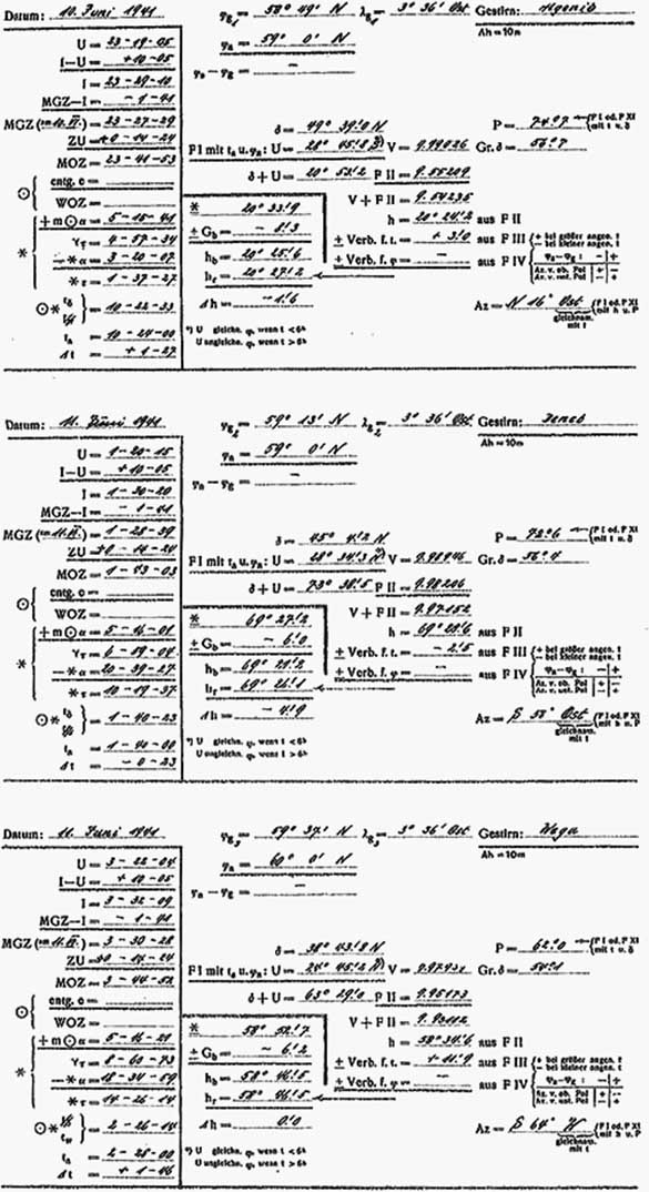
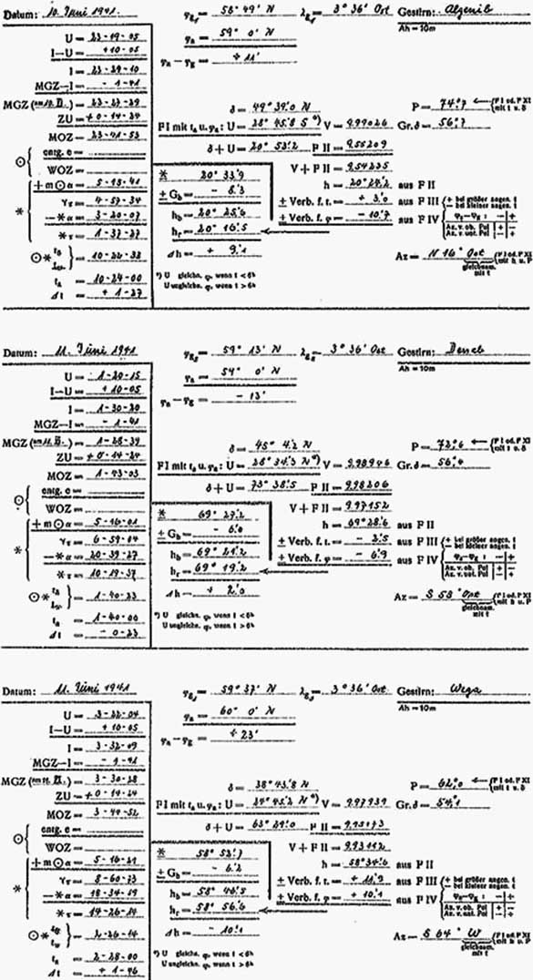
Example 4a: 3 star observations with baseline shift |
||
without Latitude correction |
||
 |
||
|
|
XIX |
||
Illustration of Example 4a |
||
 |
||
|
|
| XX | ||
Example 3b: 2 sun observations with baseline shift |
||
and Latitude correction |
||
 |
||
|
|
XXI |
||
Illustration of Example 3b |
||
 |
||
|
|
| XXII | ||
Example 4b: 3 star observations with baseline shift |
||
and Latitude correction |
||
 |
||
|
|
XXIII |
||
Illustration of Example 4b |
||
 |
||
|
|
Notes on Table F I |
||||||||||||||||||||||||||||||||||
 |
||||||||||||||||||||||||||||||||||
| Table F I Notations | ||||||||||||||||||||||||||||||||||
|
||||||||||||||||||||||||||||||||||
| Notes | ||||||||||||||||||||||||||||||||||
| To determine P find the table with a set of columns matching the assumed hour angle. Enter the table with declination on the left or right and take the value of P. If P is below the dotted line use table F XI. | ||||||||||||||||||||||||||||||||||
| To find U, V and Gr. find the table with a set of columns matching the assumed hour angle. Enter the table from the left or right with the assumed latitude and take the values. | ||||||||||||||||||||||||||||||||||
| To find the Azimuth: Find the closest match of P and h and read the azimuth at the bottom of the table. Hint: scroll through the tables until you find the rough values of P then use h to pick the closest match. | ||||||||||||||||||||||||||||||||||
|
|
Notes on Table F II |
|||||||||||||||
 |
|||||||||||||||
| Table F II Notations | |||||||||||||||
|
|||||||||||||||
| Notes | |||||||||||||||
| Descending on the far left column for log sin 0° (at the top of the tables in bold numbers) | |||||||||||||||
| Ascending on the far right column for log sin 179°(at the bottom of the tables in bold numbers) | |||||||||||||||
| To take the log sin of δ + U: | |||||||||||||||
| 1. Find the table with the degrees of δ + U in bold numbers on the top or bottom and enter the table on the right or left with the minutes of δ + U. Note the log sin in the degrees column. | |||||||||||||||
| 2. Calculate the difference between the log sin from step 1 and the log sin for the next higher minute. Find the exchange table (on the right of the log sin tables) with that difference on the top. Enter with the tenths of minutes on the left and note the log sin in the minutes column. Add this value to the log sin from step 1 above. | |||||||||||||||
| To determine h: | |||||||||||||||
| 1. Find the closest value of log sin of V + (δ + U) (determined in step 2 above) in one of the F II tables. Note the degrees and minutes. | |||||||||||||||
| 2. To get the tenths of minutes calculate the difference between the log sin value from step 1 and the log sin for the next higher minute. Find the exchange table (on the right of the log sin tables) with that difference on the top. Follow down to the difference between the actual V + (δ + U) and the closet value in the table. Read the tenths of minutes at the left. Add this to the degrees and minutes from step 1. | |||||||||||||||
|
|
Notes on Table F III |
||||||||||||||||||
 |
||||||||||||||||||
| Table F III Notations | ||||||||||||||||||
|
||||||||||||||||||
| Notes | ||||||||||||||||||
| To determine the correction for t: | ||||||||||||||||||
| 1. Find the table with the correct assumed latitude at the top or bottom on the left. Move up or down the column to the azimuth (interpolate if necessary). | ||||||||||||||||||
| 2. Move across the table to the right to the column corresponding to the number of seconds in Δt. | ||||||||||||||||||
| Note: "if calculated with too great an assumed t" means that Δt is positive and the hour angle was rounded up; "if calculated with too small an assumed t" means that Δt is negative and the hour angle was rounded down. | ||||||||||||||||||
|
|
Notes on Table F IV |
||||||||||||||
 |
||||||||||||||
| Table F IV Notations | ||||||||||||||
|
||||||||||||||
| Notes | ||||||||||||||
| These two tables allow one to work either with an assumed position or with a dead reckoning position. | ||||||||||||||
|
|
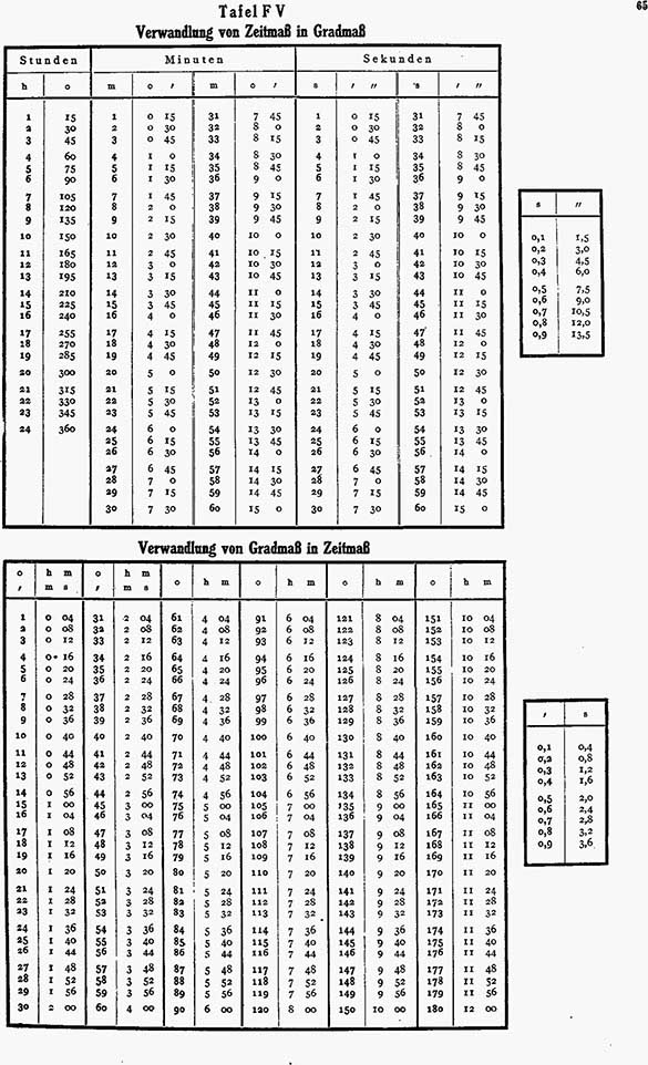
Notes on Table F V |
||||||||||||
 |
||||||||||||
| Table F V Notations | ||||||||||||
|
||||||||||||
|
|
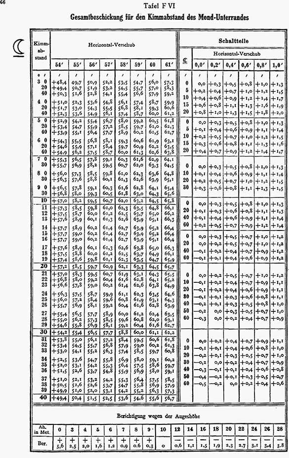
Notes on Table F VI |
||||||||||||||||
 |
||||||||||||||||
| Table F VI Notations | ||||||||||||||||
|
||||||||||||||||
| Notes | ||||||||||||||||
| Table F VI gives the total adjustment for refraction, semi-diameter and parallax to be applied to the altitude with a supplementary table for height of eye. | ||||||||||||||||
|
|
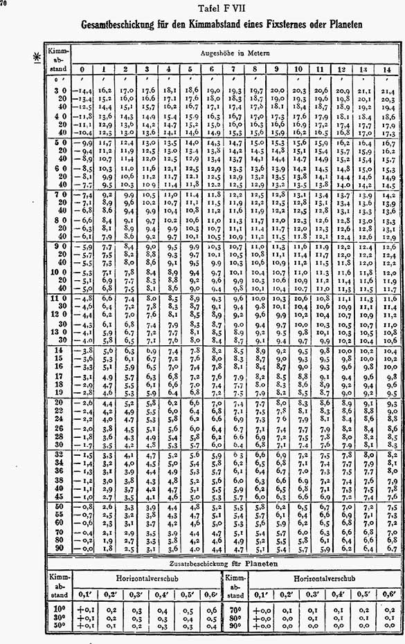
Notes on Table F VII |
||||||||||||||
 |
||||||||||||||
| Table F VII Notations | ||||||||||||||
|
||||||||||||||
| Notes | ||||||||||||||
| Table F VII gives the combined correction for refraction and height of eye (0-30 meters) to be applied to the altitudes (3°-90°) of fixed stars or planets. | ||||||||||||||
To find the total correction for stars and planets: |
||||||||||||||
| 1. Enter the table with the uncorrected sextant observation on the left. Move to the right to the column for height of eye. Interpolate as necessary. | ||||||||||||||
| 2. Additionally for planets, enter the table at the bottom of the page with the uncorrected sextant observation on the left and move across to the column for the horizontal displacement (from the Almanac) take the correction and add it to that from step 1. | ||||||||||||||
|
|
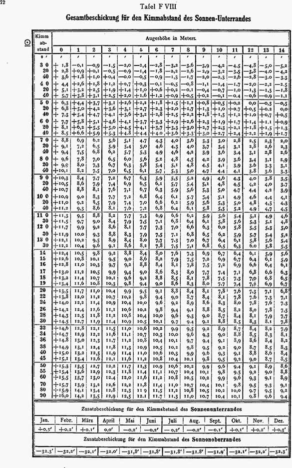
Notes on Table F VIII |
||||||||||||||
 |
||||||||||||||
| Table F VIII Notations | ||||||||||||||
|
||||||||||||||
| Notes | ||||||||||||||
| Table F VIII gives the correction for refraction, semi-diameter and height of eye (0-30 meters) to be applied to altitudes (3°-90°) of the sun's lower limb; there are also two auxiliary tables to provide corrections to the altitudes to take care of the varying semi-diameter of the sun through the year, and for the case where the sun's upper limb was observed. | ||||||||||||||
|
|
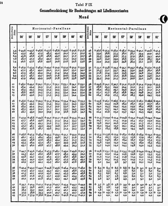
Notes on Table F IX |
||||||||||
 |
||||||||||
| Table F IX Notations | ||||||||||
|
||||||||||
|
|
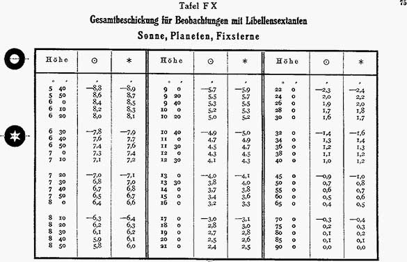
Notes on Table F X |
||||||||
 |
||||||||
| Table F X Notations | ||||||||
|
||||||||
|
|
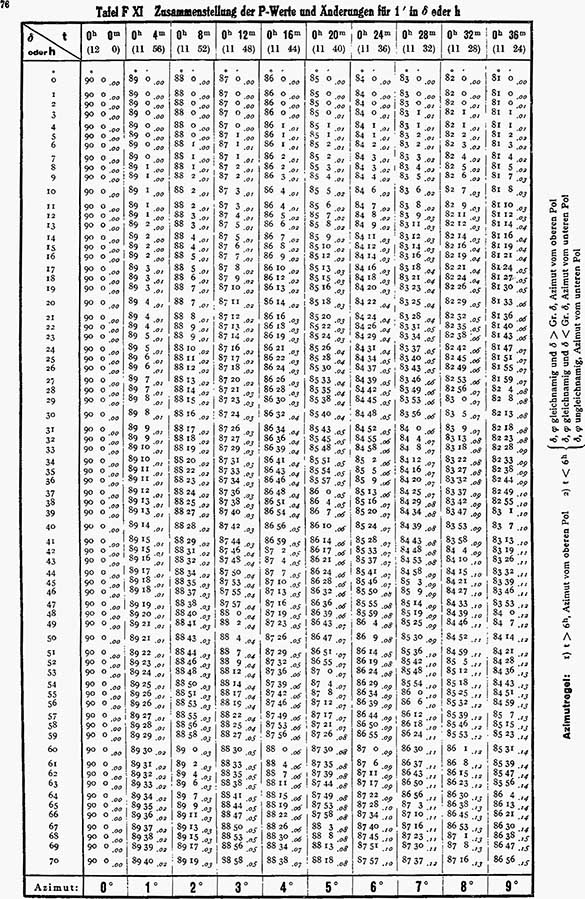
Notes on Table F XI |
||||||||||||||||
 |
||||||||||||||||
| Table F XI Notations | ||||||||||||||||
|
||||||||||||||||
| Notes | ||||||||||||||||
| To determine P: | ||||||||||||||||
| 1. Enter the table with the whole degrees of declination and the assumed hour angle and take P in degrees and minutes. Note the change value for each minute of declination. | ||||||||||||||||
| 2. Multiply the change value times the minutes of declination and add the resulting minutes to P to give the final P value. Note: P is in degrees and tenths of degrees not degrees and minutes. | ||||||||||||||||
| The table on Page 88 is simply an exchange table to calculate step 2 above. To use it: | ||||||||||||||||
| 1. Enter the table with the minutes of declination on the left and first the tenths of the change value on the top. Take the resulting minutes. | ||||||||||||||||
| 2. Enter the table with the minutes of declination on the left and the one hundredths of the change value on the top. Add the resulting minutes to step 1 above. | ||||||||||||||||
|
|