 |
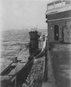
Photo 1: General view - Deck hatches open to show forward external torpedo stowage tank | 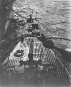 |
Photo 2: View forward from bridge showing 88 mm. gun and circular cover over forward marker buoy stowage - Note training and elevating wheels on both sides of gun |
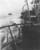 |
Photo 3: View looking aft from bridge - Note welded construction of ballast tank |
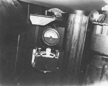 |
Photo 4: View of forward end of bridge showing gyro repeater, rudder angle indicator, altiscope housing - Note voice tube outlet |
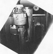 |
Photo 5: View on bridge looking forward: showing binocular pedestal in foreground - This equipment apparently intended for use as a director for firing torpedoes from the bridge. Lever on right of pedestal believed to be firing lever (Binoculars not mounted) | 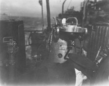 |
Photo 6: View on bridge looking aft: showing top of attack periscope sticking just above top of periscope support, gyro repeater mounted on and forward of periscope support, barrel of 20 mm. A.A. gun in background, and A.A. gun barrel stowage cylinder at left |
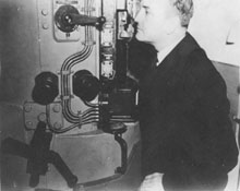 |
Photo 7: View in Conning Tower looking aft showing housing of "fixed-height of eye" attack periscope - Operator is seated on seat secured to housing and controls by hydraulic power training with his feet |
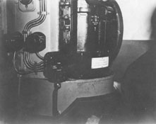 |
Photo 8: Conning Tower - "Fixed-height of eye" attack periscope (Eye piece is at "A" at top edge of photograph) |
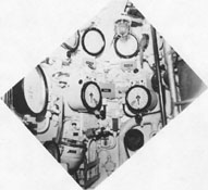 |
Photo 9: Conning Tower looking forward - Ladder to bridge shown at right | 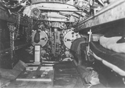 |
Photo 10: Forward Torpedo Room showing torpedo handling beams; crews bunks, and, in background, four bow tubes - Six spare torpedoes in this space (a lower row of four and an upper row of two immediately below temporary false wooden deck between and at the level of the lower tiers of bunks) |
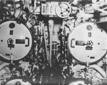 |
Photo 11: Forward Torpedo Room showing, at top center, Gyro-angle receiving and setting instrument - Hand wheel shown is used to set gyro angles on loaded torpedoes | 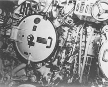 |
Photo 12: Forward Torpedo Room showing breech end of port upper tube - Vertical shaft in background is drive shaft from air operated windlass and capstan motor which is located in the bilge on the center line |
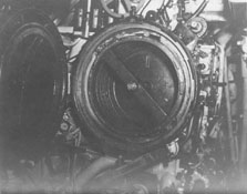 |
Photo 13: Forward Torpedo Room showing breech door of port upper tube (open to show torpedo firing piston) - Impulse air passes from oblong port (at about one o'clock), around edge of piston skirt, to the back of the piston | 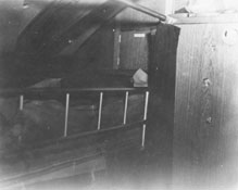 |
Photo 14: Warrant Officers' Space - Two-high bunks on starboard side |
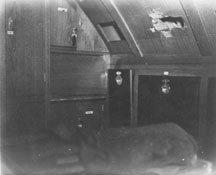 |
Photo 15: Wardroom (after port corner) - Sea bag in foreground is on single transom bunk on port side of wardroom | 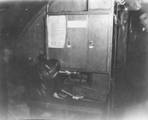 |
Photo 16: Captain's Room looking forward - Bunk is outboard of desk |
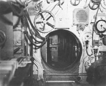 |
Photo 17: Control Room looking forward - Large hand wheel above and to left of circular door is for operation of vent of forward M.B.T. (No. 5) | 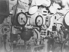 |
Photo 18: Control Room (forward starboard corner) showing at (A) Gyro repeater, (B) Sound-powered telephone, (C) Echo Sounding Instrument, (D) Pitometer log, and (E) Support frame for connecting CO2 absorbent canisters to ventilation system - Engine order telegraphs shown |
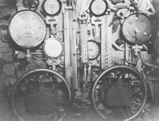 |
Photo 19: Control Room starboard side forward showing diving plane controllers, hand wheels for manual operation of diving planes, diving plane angle indicators, Bourdon tube type shallow diving depth gauge, closed end tube type "attack" depth gauge, closed loop inclinometers (one with coarse graduations and one with fine graduations), and propeller r.p.m. indicators - Case of deep diving depth gauge is shown at right of photograph - A mechanical diving plane indicator can be seen back of each diving plane hand wheel | 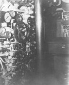 |
Photo 20: Control room (at about midlength of starboard side) air manifolds - Large hand wheel is master control for tank blow manifold below it - Flask manifold is just to left of large vertical tube in the photograph - Service air manifold is obscured by the vertical tube which is the direction finder loop tube - Three of the hand wheels of the engine exhaust M.B.T. low pressure blowing system shown at top left - Hull opening indicator board and compartment ready light board show at top right |
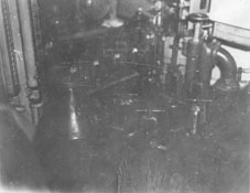 |
Photo 21: Control Room (starboard after corner) Drain manifold - Pump end of vertically mounted centrifugal drainage pump shows in background, and lower end bell of the drive motor shows at top of the photograph | 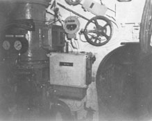 |
Photo 22: Control Room (looking aft) - Drain pump shown at left |
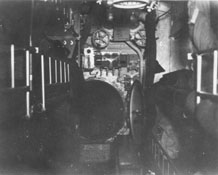 |
Photo 23: Petty Officers' Quarters looking forward toward door to control room | 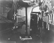 |
Photo 24: Petty Officers' Quarters looking aft |
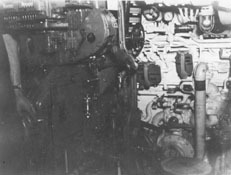 |
Photo 25: Engine Room showing forward end of port engine | 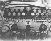 |
Photo 26: Engine Room looking up and aft to show gage board at forward end of engine room - Large hand wheel at lower center is inboard engine air induction valve hand wheel |
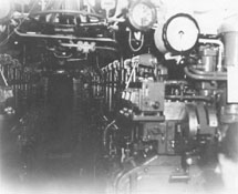 |
Photo 27: Engine Room looking aft | 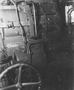 |
Photo 28: Engine Room - After end of port engine showing supercharger and, at lower left, the engine clutch operating hand wheel (Clutch can also be operated by air pressure from 12 atmosphere service air system) |
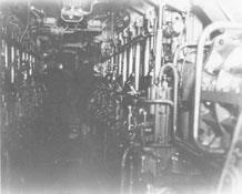 |
Photo 29: Engine Room looking forward from after end | 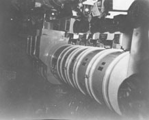 |
Photo 30: Motor and After Torpedo Room showing main motor controls on port side (starboard side similar) |
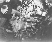 |
Photo 31: Motor and After Torpedo Room (starboard side about midlength) showing opposed piston crankless diesel air compressor | 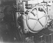 |
Photo 32: Motor and After Torpedo Room (port side at about midlength) showing forward end of port high pressure air compressor (4 stage motor driven) - Hand steering wheel shown in its stowed position |
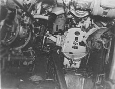 |
Photo 33: Motor and After Torpedo Room showing breech door of the single after tube. Steering motor and its gear box show at top right |